Smart microprocessor-based devices have been developed
by a number of leading vendors. Advanced monitoring and
control technology for ESD valves has made PSTs more effective
and easier to implement, helping to better balance the need
to achieve higher pipeline integrity and safety. This includes
considerations, such as spurious trip rate, initial investment and
ongoing operational costs, system integration and documentation
requirements.
Today’s intelligent valve monitoring and automation solutions
allow pipeline operators to achieve high SIL levels while delivering
a greater diagnostic coverage factor, flexibility in implementing
and scheduling PSTs and improved communications. There are a
number of popular methods for partially stroking valves, and each
has its advantages and disadvantages.
The most common techniques include:
)
)
Mechanical jammers.
)
)
Digital valve controllers (smart positioners).
)
)
Digital control transmitters.
Mechanical jammers are the simplest and least costly
option for automated local or remote PST functions, but they
involve a manual process. These devices are used in cases where
accidentally shutting the valve would have severe consequences
or any application where the end user prefers a mechanical
solution. The jammer is integrated in the design and is intended
to limit valve movement, linear or rotary when placed in position
with a key. There is a major disadvantage with mechanical
jammers if an ESD event occurs during the PST test interval. The
need to manually place the jammer can also cause the valve to
move suddenly and violently. Human errors by field technicians
can also result in complete valve closure. Therefore, the reliability
of this technique is dependent on procedures, training, and
correct design specifications.
The digital valve controller (i.e. smart positioner) is the most
common and complex of the three PST options. It is designed to
generate an automatic PST function via an internal IP transducer
and capture dynamic diagnostic data of the test. However, the
positioner does not capture the ESD event, thus requiring the
use of additional devices, such as limit switches or position
transmitters. Also designed for automated local or remote PST,
the positioner-based approach is a proportional control style of
valve movement. It is created by the ESD system step changing
the positioner’s set point value to the PST target value. The device
monitors the speed and quality of response as well as actual valve
position. If the valve does not respond within a reasonable period
of time, the positioner’s microprocessor cancels the test.
The latest entry into the automated PST market is the digital
control transmitter. It is specifically designed to capture the ESD
event and functionally test solenoid valves (SOV). The device
generates an automatic PST function by temporarily de-energising
the ESD solenoid valve and captures dynamic diagnostic data
of the event. This low power, SOV-based solution is suitable for
both low and high pressure pneumatic and hydraulic applications.
Compatible with the HART®, WirelessHART™ and FOUNDATION™
fieldbus communication protocols, today’s digital control
transmitters eliminate position blind spots during the stroke of
a valve by supplying continuous feedback of either rotary or
linear valve position. Thus, they are a cost-effective alternative to
positioners for SIS applications requiring service up to SIL3.
The digital control transmitter is essentially a position
transmitter with a solid-state relay, which the SIS logic solver goes
through and powers the ESD solenoid valve. When it receives a
partial stroke test command, it opens the normally closed solid
state relay and de-energises the ESD solenoid valve until a partial
stroke position is met. Then, the relay closes again to the standard
position, the solenoid returns to fully energised and the value
goes to 100%. Because the digital control transmitter captures
the ESD event, it is never ‘blind’ like other solutions. As with any
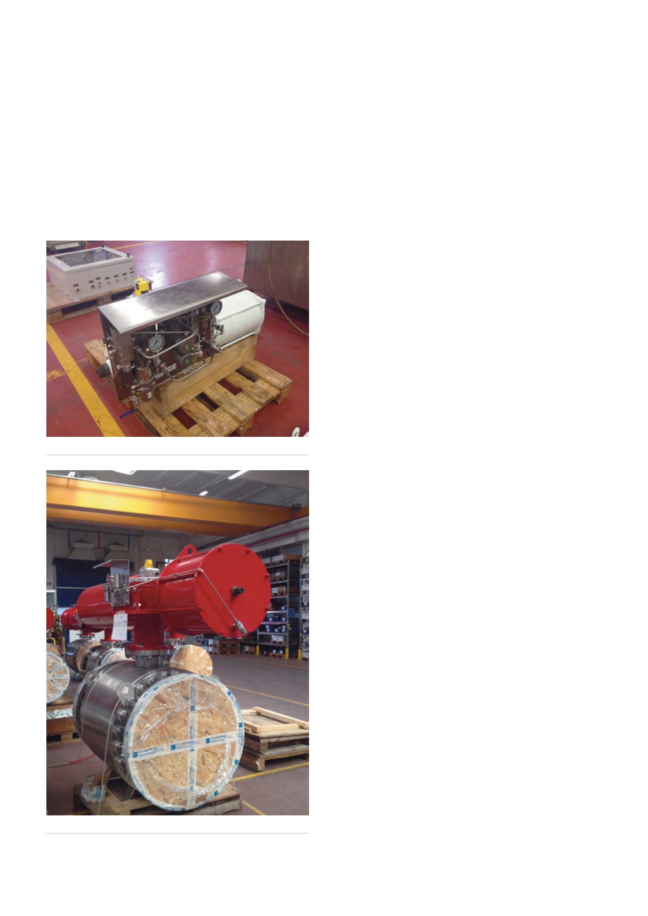
Figure 3.
Complex control manifold.
Figure 4.
Automated ball valve.
104
World Pipelines
/
JUNE 2015


