may rise and the pig might again stall in the line. And as to the
inspection tool, it will require a very dependable system for data
collection, data storage and power supply to make a successful
pig run.
With a number of pig runs that take about one month each
and the various onshore and offshore mobilisations, this project
turned out to be a unique case where the actual field work and
run time of the pigs exceeded the post processing and data
analysis. After ample considerations, cleaning with the aid of
chemicals was discarded and the pipeline was cleaned with a
relative soft and flexible bidi pig. Since the inspection technology
chosen was high resolution MFL, it was anticipated that the
inspection tool would be forgiving towards a sub-optimally
cleaned line and still collect useful data. After successful cleaning
of the line, a caliper tool was run to collect the geometrical data.
This data was first analysed to make sure that no unforeseen
features were in the line that could prevent a safe passage of the
intelligent pig. The MFL tool required special preparation. The
board computer and sensor pads were subjected to a real full
scale test, to make sure that the system would operate without
flaw for a continuous period of one month. The power packages
were specially designed, using special circuits and multiple fuse
and safety system to make sure that the system could never
generate unsafe current modes.
Finally, the pig was launched and after a total run time of
700 hours it was received in perfect condition. The tool had
collected
>
99.9% data, all of it of good quality. This extreme case
history of low-flow pipelines has proven that these lines are now
within the realm of piggable pipelines.
Bidirectional pigging
A customer of Pipesurvey International operates a long distance
oil transmission line in Central Europe with intermediate pumping
stations and tank storage. The pipelines towards the storage
tanks are 30 in. and vary in length from 100 - 500 m. Most of the
pipeline is buried, having 1.5D radius bends. The pipeline has no pig
traps – oil is pumped from the central pumping station towards
the storage tanks and it flows back by gravity.
In order to get a complete assessment of the pipeline
integrity, it was decided to conduct an inline inspection. The
above ground section of the pipeline had flanged spools that
could be taken out relatively easily. A temporary pipe spool
was created that could act as a temporary pig trap. The spool is
complete with connections, flanges and attached piping and hoses
to operate in both flow directions. A temporary pump spread was
brought to place to create flow in the line from the storage tanks
towards the pumping house. The pump of the pumping house
would be used to create the reverse flow and move the tool back
towards the temporary pumping station. A real size mock of the
system was first built in the yard in order to check the MFL tool
flipover pressure and behaviour. When this was proven successful,
the system was brought to the field. Five of these pipelines were
inspected in one mobilisation. The work in the field included:
)
)
Mechanical work on all lines: removal of existing piping,
installation of temporary piping and reinstatement of the
original piping in order to bring the pipeline back to its original
status.
)
)
Operational work: inserting the pig, pig tracking and pumping;
in addition to the field work of course all lines were analysed
in accordance with the prevailing standards.
Field work on all five lines together was completed within
three weeks and all lines reported successfully. The tools operated
at flows below 2 barg pressure, including the static pressure of the
storage tanks. The project proved to be a very time-efficient and
cost-effective method for inspecting non-piggable pipelines in
tank farms, loading lines and jetties.
Multi-diameter pipelines
A great number of multi-diameter pipelines exist, which may range
from next-size diameter variations to larger and more extreme
differences. The variation may be due to valve stations, river
crossings, connection of two previously separated pipelines, or
just have been designed that way.
A major gas trunk-line in Central Europe, which transports gas
for domestic, industrial and power-plant use, is designed 32 in. but
connects to a major river crossing – already in place for a couple
of years – of 24 in. The result is a difficult configuration, where
the pig not only has to collapse from the first, large section into
the second, small diameter, but has to expand again to traverse
another 100+ km in the large diameter pipe!
The tool needs to be optimally centralised and sealing
in the last section to guarantee a successful pig passage and
measurement. A self-centralising and flexible MFL measurement
module was developed and it is pulled by a module with board
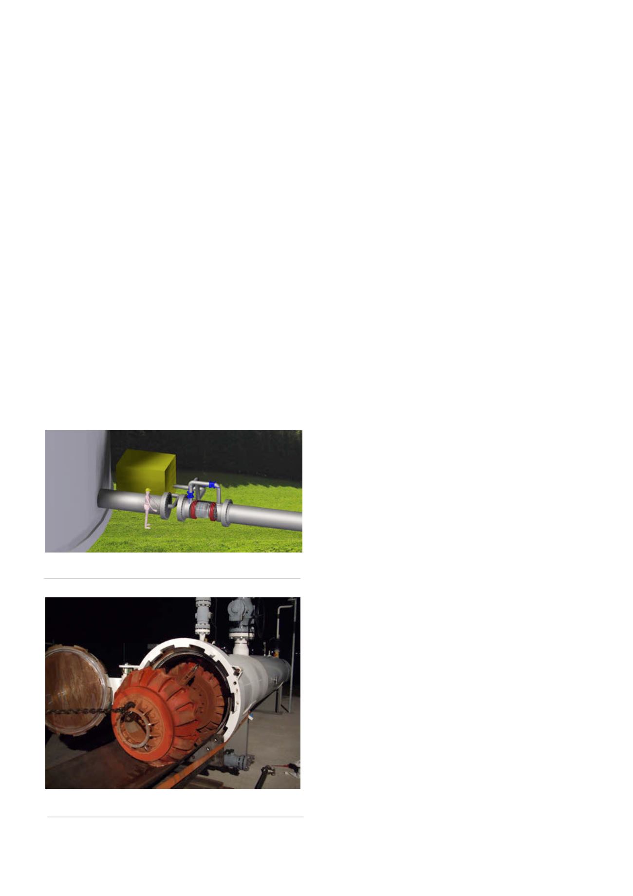
Figure 2.
A temporary pipe spool and pump spread used for
bidirectional pigging of non-piggable line.
Figure 3.
A 32 x 24 in. multi-diameter MFL being retrieved
after 153 km pig run.
50
World Pipelines
/
JUNE 2015


