accelerations, velocities and positions
over a period of time. The chute
geometry is created using CAD
software and particles are created
with appropriate coal properties and
contact interaction parameters, based
on the flow properties test results for
the coal.
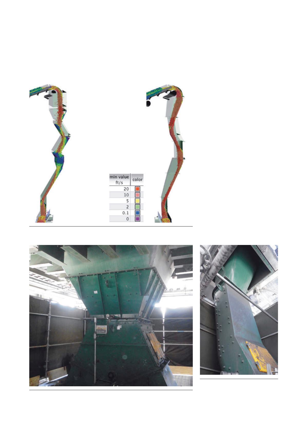
DEM analysis of the RC3 to
RC4/RC5 chute configuration showed
that the coal stream velocity was
decreasing significantly after an initial
8 ft vertical drop (Figure 6). This was
followed by several, nearly
orthogonal impacts, before entering
the diverter arrangement. When coal
was fine and had high moisture
content, these additional impacts
caused considerable slowing of the
stream. Any buildup initiation on the
chute surface was presenting
additional obstructions to material
flow. Over time, this would
eventually lead to choking of flow
(represented by blue coloured
particles in Figure 6). The DEM
simulation results were consistent
with the experience of the plant
operators.
Based on this analysis and
understanding, J&J provided
recommendations for modification of
the chute configuration to minimise
the free fall height and maintain
momentum through the coal stream
impacts. A new diverter arrangement
with larger cross-sectional area was
also recommended. The
recommended configuration offered
significant potential for improvement
over the existing configuration.
For the crusher discharge chutes,
the stream of crushed coal was
free-falling through a significant
Figure 6. DEM simulation by J&J showing flow issues (on left) and improvement (on
right). J&J’s proprietary DEM software was used for the analysis.
Figure 7. Modified discharge chute for crusher with bigger throat and steeper chute surfaces.
Figure 8. Part of modified chute
arrangement from belt RC3 to belts RC4
and RC5.
48
|
World Coal
|
August 2015


