performance. In late 2012, the plant
hired Jenike & Johanson (J&J) to
evaluate the transfer chutes. J&J
visited the plant to review the transfer
chutes and the problems.
Riad Dandan from Dominion’s
headquarters in Richmond, Virginia,
was involved throughout in
identifying the problems and
providing project direction.
Analysis and
corrective plan
Based on the initial review of
problems with these transfer chutes,
J&J recommended conducting flow
properties testing of the coal handled
at the plant. The plant had multiple
coal suppliers. The moisture content
of the coal changed quite a bit,
depending on the time of the year.
Because of this, it was decided to test
samples from a few different
suppliers and to run the tests at three
different moisture contents to cover
the range of possible operating
conditions. Various chute surfaces
were tested to determine the most
suitable chute liner surface from a
reliable material flow perspective.
Test results showed that increases
in the moisture content of coal made
the chute surfaces significantly more
frictional. This meant that, unless
sufficient slope was provided, coal
flow velocity would decrease and
could cause material stoppage and
buildup on the chute surface. Any tall
drops would result in high impact
pressures. Tests showed that
high‑impact pressures would require
considerably steep chutes to ensure
that the coal stream would not come
to a stop after impact with the chute
surface. Test results also provided
quantitative values of the chute
angles required to achieve reliable
flow. Based on the test results,
SA1750CR, a chromium carbide
overlay on steel provided by
SAS Global Corp., was selected for
the purpose of lining the modified
chute arrangements.
The information obtained from
this testing was also used to
determine the input parameters
required for Discrete Element
Modelling (DEM). J&J’s proprietary
DEM software was used to perform
the analysis. DEM is a numerical
technique used to simulate the
motion or flow of a collection of
particles. It uses laws of motion to
calculate the total force experienced
by individual particles in a bulk
material to determine their
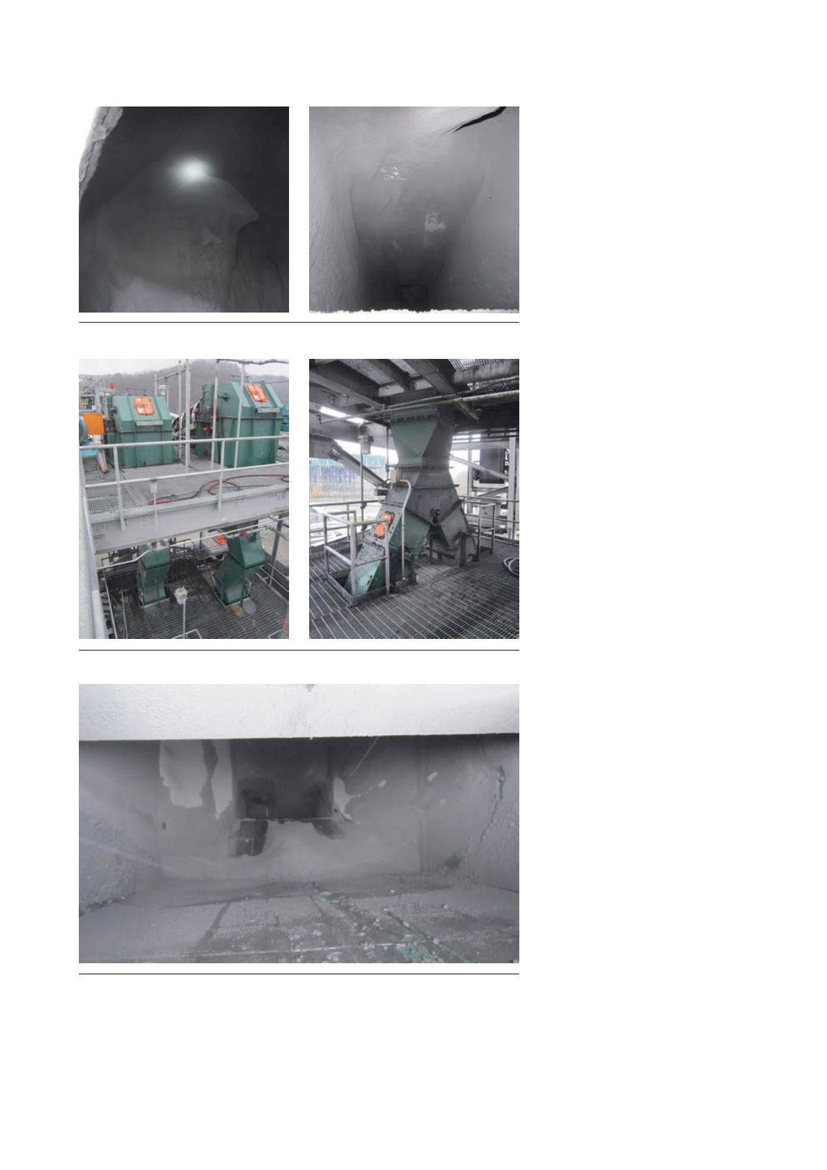
Figure 3. Buildup inside discharge chute for crushers.
Figure 4. Original chute arrangement from belt RC3 to belts RC4 and RC5.
Figure 5. Coal buildup inside chute arrangement from belt RC3 to belts RC4 and RC5.
46
|
World Coal
|
August 2015


