60 |
Oilfield Technology
June
2015
process, the industry has an excellent understanding of what needs to
be done; this is the 80%. The ‘other 20%’ is discovering ways to further
support the various aspects of well construction in detail in order to
innovate newways to drive efficiencies and cost savings.
Therefore, the 80/20 rule is applied to the unconventional shale
plays, innovation with respect to holistic reliability in the space of the
‘other 20%’ is critical in today’s low oil price environment.
Innovationof thewellhead
One key component on every well drilled is the wellhead. It is a vital
pressure‑containing component at surface that can oftenmake
operational processes more efficient and flexible. By nature, horizontal
wellbores are deviated, causing fluids and cement tomigrate to the low
side of the hole, resulting in a less than optimal distribution downhole.
Internal components, such as a rotatingmandrel hanger, will allow the
casing to be rotated through the heel of the lateral as well as ensure the
production casing runs the full length of the lateral and achieves a proper
cement job. Once the casingmandrel is landed in the wellhead, slotted
mandrel shoulders permit cement circulation, removing the necessity to
wait on cement as with casing slips.
Other options that can drive operational efficiency are back pressure
valves (BPVs) and wellhead packoff systems. These can be installed
into the rotatingmandrel to provide a barrier for both the bore and the
annulus to secure the well at surface. This is especially important to help
increase operational efficiency, as walking drilling rigs often are planned
tomove off the current well and onto the next as soon as possible.
Another important wellhead component in the completion and
production process is the tubing hanger. Frequently after a well has
been hydraulically fractured and the well flowed back and cleaned up,
production will naturally flow for a period of approximately six months.
After this time period, production often requires installing artificial lift
and setting a packer downhole. A tension hanger is one easy way of
achieving this, allowing completions to set the packer and keep the
tubing string in tension. This will help prevent rod wear and provide a
standardised solution to the completions team, who is also likely focused
on boosting operational efficiency.
An example of advances made in the area of wellhead reliability and
functionality for unconventionals is Cameron’s advancedmulti‑bowl
nested diverter snap ring (MN‑DS) wellhead system. In this wellhead,
the production casing/tubing hanger is nested within the lower casing
pack‑off. It features a nested internally locked upper hanger that
reduces the overall height of the system for easier use with skidded rigs.
This hanger can be either a production casing hanger or a tubing hanger,
providing the option to complete as a one‑stage system if intermediate
casing is not required.
Innovationof the fracktree
As operators have adopted the factory approach to drive efficiencies in
batch drilling and completions, frack tree designs have evolved, moving
away from tall vertical conventional frack trees tomore compact designs.
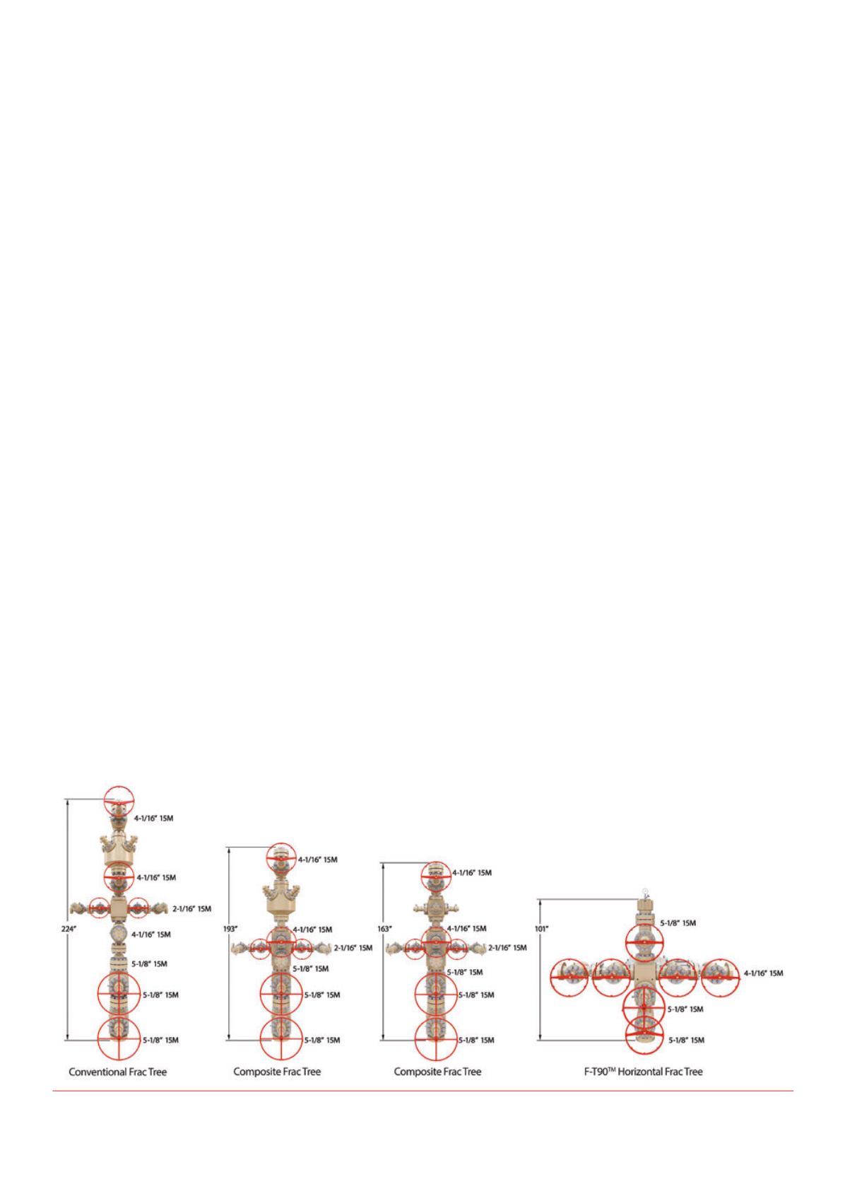
A recent move in forward‑thinking innovation for unconventional
shale plays is Cameron’s F‑T90™ frack tree. It is the industry’s first
horizontal frack tree specifically suited for today’s factory approach to
multiwell pad drilling, batch completions, and simultaneous operations
(SIMOPS) applications. The F‑T90 is engineered 50% smaller and 25%
lighter than conventional frack trees while preserving the rigorous
durability and reliability required by the industry (Figure 1).
By taking the tall vertical configuration of the frack tree and turning
it horizontally, the industry is able to take advantage of this configuration
to reduce vibrational effects of fluctuating pressure caused by the
introduction of solids flowing through frack equipment, enhancing the
integrity of overall frack operations. The 90˚ goat head is located at the
end of the horizontal section, resulting in the distance acrosswhich the
bending loads act being less than half of that of a conventional stack‑valve
frack tree. Overall, its ultra‑compact footprintmakes installation easier and
reduces bending stress at thewellhead connection.
Frack service is just about as harsh as it gets, and with the adoption
of zipper fracking, frack trees andmanifolds are being exposed to
nearly continuous service, flowing and controlling high‑pressure,
high‑volume, abrasive/corrosive frack fluid for days and weeks. To
address these issues for continuous reliability, the frack trees incorporate
metal‑to‑metal seals, feature CRA inlay in seat pockets and ring grooves,
and use zero‑chamfer flowbores tomitigate turbulence that is known to
exaggerate erosion.
These features have proved beneficial in field application; there
will no doubt bemore developments as themission toward increased
reliability continues.
Innovationof frackfluiddelivery
One factor in the evolution tomultiwell pad drilling and batch
completions is the increased time that pressure pumping crews are
spending on the wellsite. Not long ago, service providers often spent
five to seven days fracking a single well with 20 stages per well, on
average. Nowadays, pressure pumping crews are spending 20 to 30 days
Figure 1.
Frack tree technological evolutionand innovation.


