64 |
Oilfield Technology
June
2015
operation withmore than 14 frack stages per leg. A four‑person crew
and one crane were used to install the pre‑assembled system in
3 hours per leg. The rig‑up time was seen at about half of that time, or
around 1.5 hours per leg. In addition to reducing the wellsite footprint,
the systemachieved a 50% reduction in the number of needed
hammer union connections.
As the number of needed connections is decreased, reliability
of the connections is increased and the drastically reducedmaze of
flowlines and restraints will have a positive impact on safety. It is the
collaboration of the operator with the service companies in exploring
newways of delivering today’s high‑volume hydraulic fracturing
programmes that ensures reliability in operational performance.
Innovationforholistic reliability
To drive reliability into the frack programme is to understand the
erosion effects on service equipment used in today’s hydraulic
fracturing operations.
The primary type of erosion encountered with surface frack
equipment is erosion due to solid particle impingement. Frequently,
fluctuating pressure coupled with sand loaded frack fluid can damage
the structural integrity of a frack tree. Sand, acid, andmany other
erosive and corrosive elements of a frack job reduce the life of the
frack tree’s valve gate and seat. Lacking proper attention, the high
pressure variations and chemical makeup of fluids used during a frack
job can reduce the lifespan of elastomers and other soft goods in the
valves of the frack tree (Figure 2).
In order to fully understand operating conditions and erosive effects
on equipment used in hydraulic fracturing, specifically frack trees and
manifolds, Cameron has conducted extensive erosion studies. From
these efforts, Cameron has developed engineering standards to address
erosion effects andmaintenance procedures to ensure reliability of the
frack equipment. These procedures, known as FracServ™ valve integrity
protection plan, establish a sequence of activities and inspections
designed to ensure that any degradation of frack equipment is identified
and corrected before the equipment is reassigned to another frack job.
An example of this diligence helped one Bakken operator achievemore
than 99%uptime in fracturing operations.
Another example of increased frack tree uptime is the experience of
one operator starting up development in the Fayetteville Shale. Faced
with the daunting challenge of entry into a new type of exploration
combinedwith concerns about finding quality equipment and
personnel to reach the company’s ultimate goals through adherence
to strict operating standards, the operator needed to keep fracturing
operations continuouswithout unexpected shutdowns for frack tree
repairs. Use of special valves andmethodology significantly heightened
confidence in frack tree integrity. Time lost to have a newvalve brought
to thewellsite, set a plug, and replace the faulty valve is about the
time it takes to complete a frack stage. For this operator, savings from
not having to replace a faulty valve on the frack treewas valued at
approximately US$1.5million.
In the Eagle Ford, an operator achieved performance gains through
the use of comprehensivemaintenance procedures. The operator
previously had been experiencing three to four failures per week that
had cost on average about US$2.7million permonth. Since instituting
specially designed frack trees and frackmanifolds and a comprehensive
maintenance programme, this operator achieved a valve integrity
success rate of 100%on 189 frack stacks and 72 zippermanifolds.
The onus of success in exploitation and production in today’s
unconventionals is on the reliability of necessary technology to keep
the industry moving forward. Therefore, as the gap in the ‘other 20%’
is closed, both operators and service companies will be able to thrive
in a low oil price environment.
Figure 5.
One of the standard responses to these conditions has been to put
more fluid throughmore lines. But, that only adds to analready tangledmaze of
lines on thewell pad.
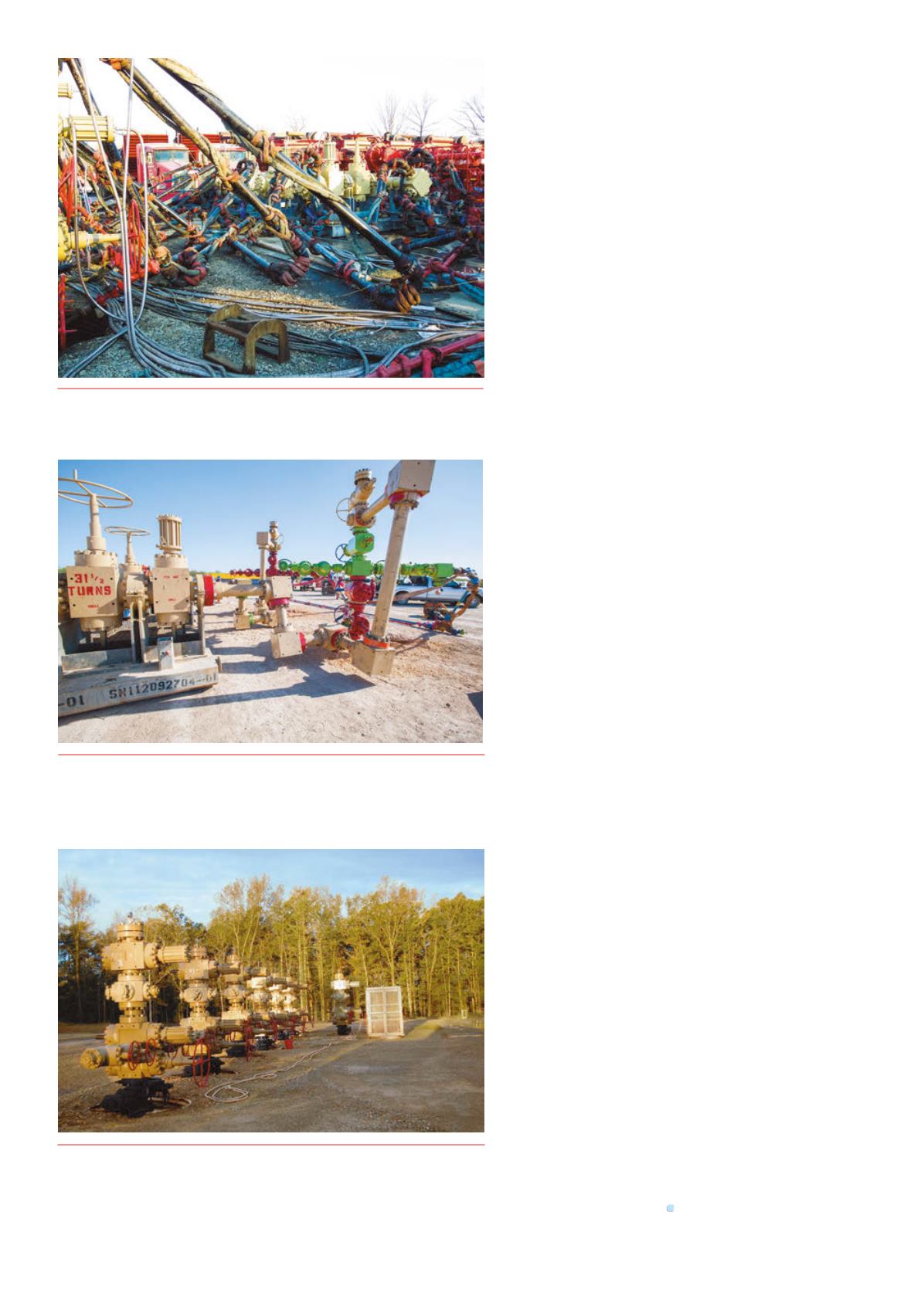
Figure 7.
FracServ™valve integrity protectionplan establishes a sequence
of activities and inspections designed to ensure that any degradation of frack
equipment is identifiedand correctedbefore the equipment is reassigned to
another frack job.
Figure 6.
One answer is Cameron’sMonoline™Frac FluidDelivery System. This
systemreplaces the need to rig-up four separate flow lines to the frack treewitha
single line featuringa large inner diameter bore to accommodate the large frack
fluid volumes required in today’s hydraulic fracturingprogrammes.


