supporting the rollers themselves. This
is another area where an opportunity to
make huge cost reductions is often
missed.
Idler rolls need to be supported by a
structure (usually steel). There is a
tendency to get the supplier of the rolls
to provide a support structure and then
the designer of the system provides a
steel structure to hold up the idler
support structure rather than look at
synergies in the support arrangements.
Combining the two is obvious and
should be considered.
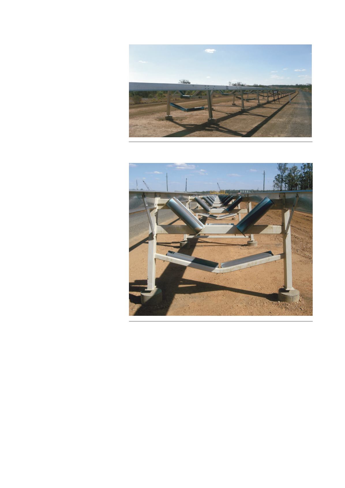
In the instance depicted here, there
were also a number of other
considerations behind the structural
design. This conveyor needs to be
roofed against rainfall and shielded
from wind to prevent dust liberation
from the stream.
An early safety risk review identified
the need to provide guarding at the
roller and belt interface. The structure
depicted in Figure 1 solves all of those
issues. On the wing idlers, where the
belt approaches the idler roll, the
structural framing is deliberately
situated close enough to the belt to act
as the finger guard.
The longitudinal rails of the
conveyor structure support the roof,
provide the side guard to prevent wind
and rain from entering the belt, and act
as the cable tray for the instrumentation
cables.
Selecting a drive system
There are a number of options for
powering a conveyor. One big drive
could do it. A single 4.5 MW gearless
drive is an obvious choice; one big low
speed motor with no gearbox. There are
many reasons why the use of those
large drives is not an optimised
solution.
The right answer to the number of
drives is a complex balancing act. The
belt itself is a large cost in the conveyor
and the single big drive results in the
highest belt operating tension – and
therefore the most expensive belt. The
big gearless drives are themselves very
expensive. At the time of writing this
paper, a pair of squirrel cage 2250 kW
motors and heavy gear reducers are
actually substantially cheaper than a
single gearless motor that delivers the
same power output. The smaller drives
offer the advantage of being able to be
installed on separate drive pulleys,
which means the take-up tension could
be halved, and the overall belt tension
is reduced accordingly, saving more
money. Should one of the drives fail,
the conveyor can continue to operate at
reduced capacity while a replacement is
mobilised.
Can that logic be extended to three,
four or more drives? The answer is a
qualified yes. The lowest belt tension is
achieved by the use of many drives.
The more you employ, the lower the
peak belt tension (distributed drives
along the length of the conveyor allows
a substantial reduction in peak belt
tension). This situation does have a
limiting return. More pulleys and the
need for more distributed electrical
infrastructure all have a cost associated
with them. The drives need to be in the
belt carry strand and that means the
need for trippers, which in turn means
more transfer points and therefore more
belt wear.
In this example, the optimum
solution would be a primary drive near
the head pulley, carrying two 1100 kW
drive motors, another 1100 kW drive on
a secondary pulley adjacent to the
Figure 1. An integrated overland conveyor structure with widely spaced idlers and
combined support details.
Figure 2. Overland conveyor structure with integrated idler roll and structural supports.
July 2015
|
World Coal
|
33


