drum was positioned on the on the deck of a work boat
from where the liner was unspooled.
A feeder cable was fired through the pipeline during
the final cleaning and gauging procedure, which was used
to pull back through the liner installation winch cable
for connection to a towing head that was located on the
leading end of the liner.
Engineering determined the specific winching loads
necessary for the liner insertion using predictive IFL
software. The winch packs used for installation came
equipped with load cells and override devices to interrupt
operations in the event of greater than predicted loads
during the winching. The operator could also set the
devices to cut out automatically at a given load if the
engineered safety factor relative to the liner yield strength
were approached. In this instance, however, and as with
most 0.5 - 5 km liner insertion calculations made, the
forces actually incurred proved to be no more than one-
tenth of the liner’s ultimate tensile yield strength.
Installation of IFL end termination coupling devices
at riser flange locations concluded the liner installation
process. After the IFL was drawn through the entire
pipeline length, the liner was then pressurised to inflate
it. The liner, being manufactured to fit the diameter of the
host bore, then expanded to form an intimate fit with the
inner wall of the pipe.
Installation of the IFL end termination connectors,
which ensures reliable compression seals and restraint
at the liner ends, followed liner inflation and fitting
process. Hydrotesting the relined pipe certified that
the rehabilitated pipeline system was now ready for
recommissioning and return to operation.
Petronas estimates the service life of these lines to
have been extended by at least 30 years.
Manufacturing
IFL materials are manufactured under strictly controlled
conditions. Only raw materials of the highest quality from
approved specialist suppliers are selected and utilised,
having first been subjected to vigorous quality control
and testing, in full conformity with a detailed IFL liner
manufacturing and test plan.
Every element of the manufacturing procedure is
carefully and continuously monitored and controlled
with real time computer assessment and feedback so
as to ensure absolute precision. Once commenced and
stabilised, the manufacturing process is a smooth and
constant process until the full length of the desired liner
has been produced. Every facet of the liner production
quality assurance is recorded and the produced liner
quality is thereafter further verified by extensive testing
prior to factory acceptance and certification. Finally, the
liner is dispatched to the customer.
IFL is reeled flat packed, onto specialist shipping drums
designed to be containerised in conventional high cube
containers, with each drum capable of taking up to 5 km of
liner, dependent upon diameter.
At the moment the production tooling is available for
the 6 in. and 8 in., with 10 in. and 12 in. planned for early
2016 and thereafter ultimately up to 18 in.
IFL applications
IFL offers the pipeline industry a viable, fast and
economical option to new-lay pipeline replacement. IFL
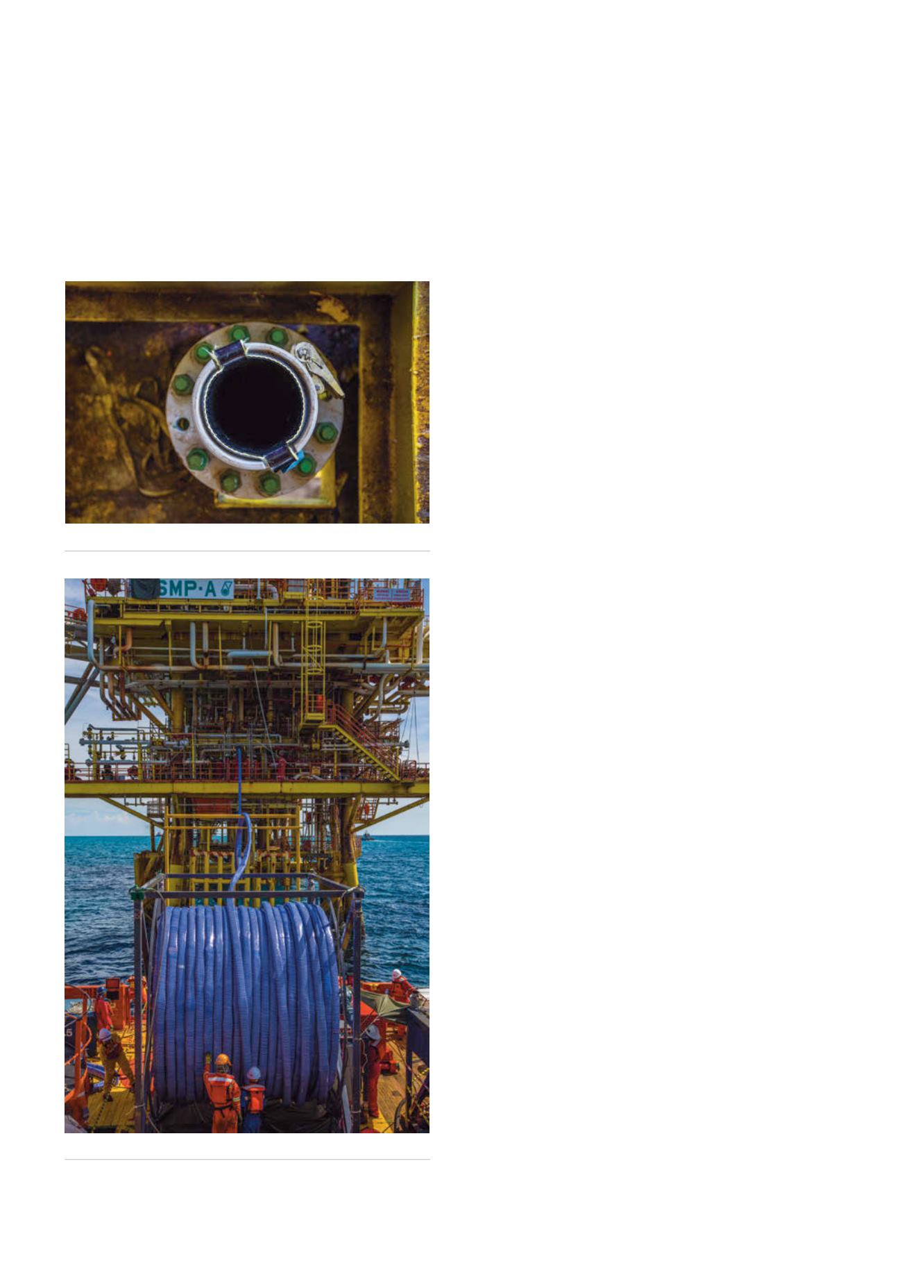
Figure 7.
Liner insertion.
Figure 6.
Liner re-rounded before end connector installation.
64
World Pipelines
/
JUNE 2015


