data into length, depth, and width measurements for each
anomaly through complex algorithms, neural networks, and
years of experience. The output report allows the operator
to have further understanding of their pipeline asset
and can integrate the ILI data with other pertinent data
sources that impact pipeline condition such as corrosion
protection, soil type, material type, history, location, etc.
Even higher resolution
Baker Hughes continues to develop the technology to
better identify and quantify pipeline anomalies. The
recently launched Baker Hughes VECTRA AFI inspection
tools combine circumferential and axial MFL to accurately
manage multiple pipeline integrity threats. However, while
MFL ILI technology is a great method for detection and
sizing of general corrosion, it has limitations with some
common pipeline defects, as defined by the Pipeline
Operators Forum, such as pinholes and pits.
After identifying this gap, Baker Hughes focused on
improving the resolution in the Baker Hughes VECTRA and
GEMINI MFL tools through further sensor development.
The Baker Hughes triaxial sensor design remains a leading
method for defect identification and classification, with
confirmation that the three axis approach to measuring
flux vectors was the most beneficial methodology.
How can the resolution be improved? The most
efficient method is to increase the number of data points
being collected during the inspection. While this seems
obvious, there are numerous mechanical, electronic, and
software hurdles to overcome to reach that objective.
Still, Baker Hughes set out, and successfully increased the
number of sensor triads from three to seven in each sensor
‘head’ to provide even higher resolution for operators.
Baker Hughes started with the current head design,
which houses the sensors and facilitates the close
connection between the sensor and the pipe wall for
flux measurement. This design measures approximately
1 x 1 in. (25 x 25 mm), leaving little space for additional
Hall sensors, wiring, circuitry, and an Eddy coil (which
determines defect locations relative to the pipe wall both
internally or externally). However, Baker Hughes wanted
to maintain the head size to allow easy integration of any
new sensor to the existing tool fleet so that customers
could have quick access to the new technology without
additional mechanical impact to the fleet. So what is
needed to squeeze 133% more technology into the same
space?
The advances in electronic packaging techniques
made available by the advances in portable electronics
allowed the company to use these developing electronic
technologies when it came to improving sensor density
with the MFL sensor head. At the start of the design
project, a large number of constraints were imposed upon
the successful design, including the following:
)
)
Reduce the power consumption of the sensor head,
while more than doubling the number of sensors.
)
)
Keep the same physical dimensions and pass all of the
same standard temperature and pressure testing as the
existing proven standard sensor head design.
)
)
Improve the
orthogonality of the
signals with respect
to axial, radial, and
circumferential MFL.
The manufacturing
of the triaxial sensor
cubes was developed
in conjunction with a
product development
company using a unique
process for designing
and manufacturing three
dimensional electronic
circuits. To achieve the
increase in sensor density
that was desired, the cubes
have a number of unique
and interlocking features
built into them.
However, building the
sensor cubes was only
one half of the battle. The
signals from the sensors
had to be captured and
recorded on the smart pig.
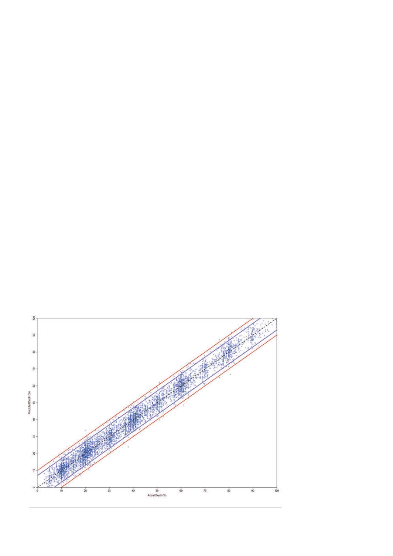
Figure 2.
Unity plot showing tool predicted depth vs actual depth.
42
World Pipelines
/
JANUARY 2015


