combination with a recycling machine because it does not
have extra additives, which can obstruct the screens. The
drilling fluid was checked continuously during mixing, upon
return to the recycling unit, and then finally when it came
out of the recycler. When necessary, the mud-engineer
could instruct to adjust the bentonite content, increase it or
dilute it.
For the lubrication of the tunnel, Tunnel-gel Plus in
combination with some additives was used. PAC-L has been
added to give a stronger filtercake in the several formations,
which had to be passed. When the formation became too
coarse, a fibre (IPR-007) in combination with the PAC-L was
added to the bentonite, which sealed the coarse formation
completely. The fibre fixes the coarse formation and creates a
kind of spider web, reducing the pores). The bentonite and the
PAC-L can easily attach themselves to the fibre and seal the
formation.
During the drilling it was noted that, when adding a
lubricant (IDP-605) to the bentonite, the friction was reduced
by half. In addition to using the correct type of bentonite, the
total fluids system resulted in extremely low pushing forces
and drilling speeds of up to 40 m/day.
Inter-jack stations: available but not used
Since the geological conditions were expected to be complex,
it was decided to install inter-jack stations at approximately
every 150 m. In case of unexpected circumstances, which could
cause temporary increase in pushing force, then the inter-jack
stations would be available for support. However, none of
the stations has been required for such complementary push
force. Only after a temporary suspension of the pushing during
replacement of the cutting disks the inter-jack stations were
used to assist in the resumption of the pushing.
Underwater cutting disks replacement
At a distance of 178 m from the starting point, it became
clear that the cutting disks needed replacement. As the
disks are placed in front of the machine, whilst the machine
is submerged under the river’s soil, divers had to enter the
machine’s head front door to access the disk slots and replace
the disks.
Stringent safety requirements
The HSE requirements for an accessible subsurface tunnel
of this length were obviously significant and stringent.
Maintenance and inspection crew were entering the tunnel on
a daily basis, up to the machine at the end of the tunnel. For
the purpose of increasing safety, A.Hak Drillcon has used an
entire range of navigation, survey and monitoring technology
from Herrenknecht’s subsidiary VMT. Using IRIS.microtunnel,
a webbased data management and monitoring system, it was,
among other things, possible to permanently monitor all
support pressures while comparing them in parallel with the
fluctuating tides of the Elbe.
The safety concept of the site is realised through the
communication infrastructure HADES: The wireless and fibre-
based system is a supplier of video images and gas detection
values, provides the network connection for the installed
geoscanne, equips the staff on site with mobile phone and
integrated gas and fire alarm and provides an access control
into the shaft via RFID tags.
Gas pipelines pull-in
Upon completion of the concrete tunnel, the two 750 mm gas
pipelines were pulled into the tunnel with assistance of one of
A.Hak Drillcon’s HDD rigs. The drill rod was led into the tunnel,
connected to the pulling head of the pipelines, and supported by
carriages, the pipelines were pulled into the tunnel towards the
HDD rig.
Grouting after completion
When the pipelines and the HDPE conduits assembly had been
pulled into the tunnel, a final inspection took place. Then upon
acceptance of the pull-in operation, the empty space between the
assembly and the tunnel was filled entirely with grout, rendering
two gas pipelines and the conduits as encased in one solid
concrete underpass under River Elbe.
A high profile project
A high profile project has been completed successfully. This
tunnel ranks amongst the largest microtunnelling projects in the
world!
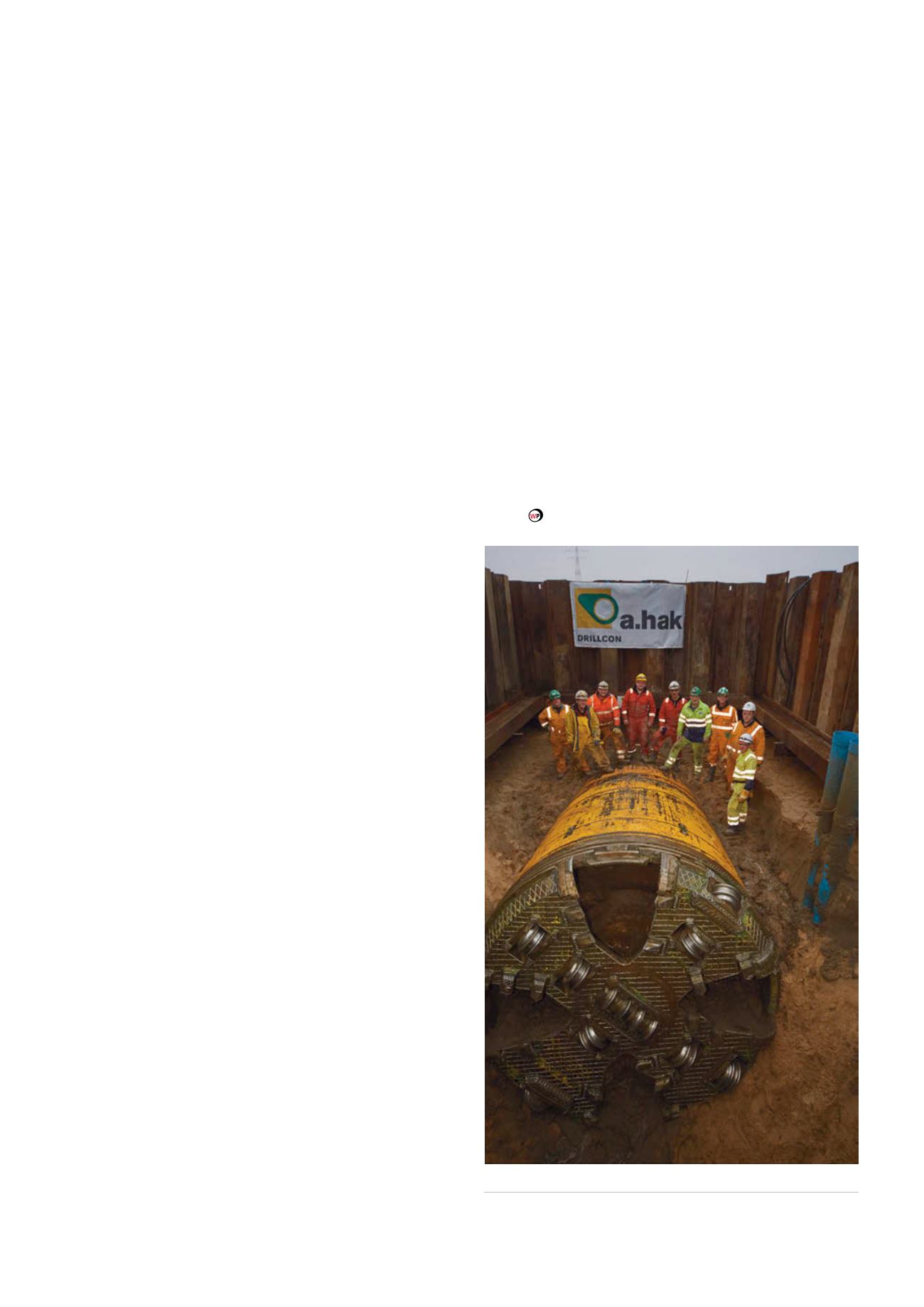
Figure 3.
Emerging in the reception shaft on Lühesand Island.
AUGUST 2015
/
World Pipelines
151


