HYDROCARBON
ENGINEERING
68
which effectively allow heat to flow from the
foundation upward creating a barrier to protect the
base and underlying soil from freezing. Electrical
heating cables are generally embedded within the tank
base foundation via conduits uniformly arranged across
the horizontal plane of the tank base. There are several
critical factors in the design of any cryogenic tank base
heating system which must be considered to ensure
safe and reliable operations. Eltherm has designed and
been involved in the successful installations of several
LNG tank foundation heating systems and below
outlines some of the critical steps in the design and
implementation phase of a tank heating system.
Heat tracing design
International standards provide guidelines and set
minimum requirements for the construction of onshore
LNG plant equipment, which include the tank base
structure and protection methods used to prevent
frost heave of the foundation.
2,3
A successful tank
foundation heat tracing system design must
incorporate and consider a number of key
requirements, including the characteristics of the tank
base, LNG tank structure as well as local atmospheric
and site conditions.
Tank base heating design begins with detailed
modelling of the heat flow and distribution of the
applied heat tracing within the concrete structure. To
accurately determine heat loss and optimum heat
transfer scenarios, eltherm design engineers utilise two
and three dimensional finite element analysis (FEA)
simulation software technology. These state of the art
tools provide the engineer with critical information,
including the visualisation of various heating system
construction scenarios and failure analysis simulation
of the system being designed.
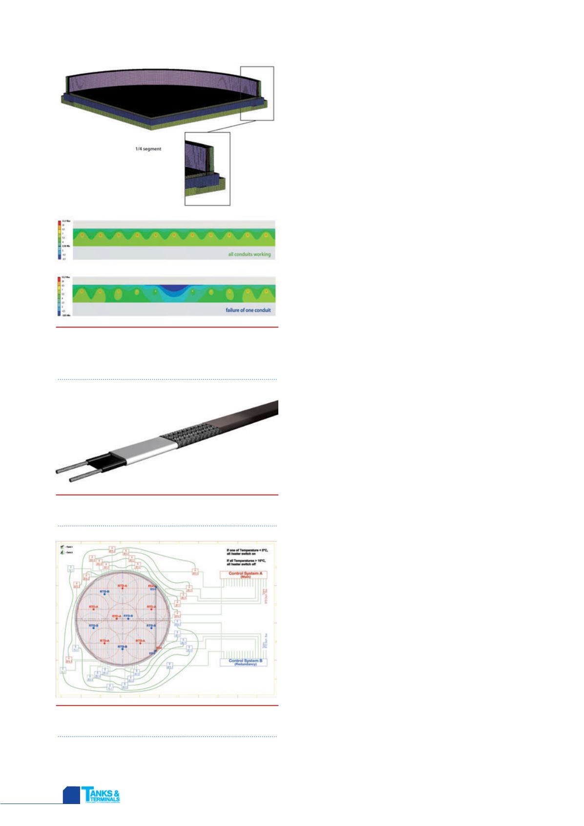
Figure 1 provides simulation details of a recent
eltherm LNG tank base heating project. FEA modelling
allows the heat tracing engineer to simulate various
operating and failure mode conditions, and provides
crucial data for designing the optimum heat tracing
layout. LNG tank designs which incorporate a concrete
ring wall typically require a ring wall heating circuit to
counter convective heat losses from the outside of the
wall and the foundation edge of the structure.
An electrical tank foundation heating system
requires 100% redundancy, meaning the system must
continue to operate if the primary heating zone(s)
suffer from a partial or complete failure. The
monitoring and control system of tank base heating
systems must be carefully designed and integrated into
the overall scope to ensure that data is transmitted
rapidly to provide the operator with information
necessary to take corrective action as required.
Heating cable selection
The selection of a suitable heating cable or heat tracer
for the application is a critical step when designing a
heat tracing system. Heating cable manufacturers have
developed various technologies, ranging from series
resistance to parallel constant wattage and self
regulating heating cables, capable of providing a
Figure 1.
Simulated 3D temperature profile of
tank base foundation and 2D temperature profile
of slab heating in normal operating and failure
analysis mode.
Figure 2.
eltherm self regulating heating cable
ELSR.
Figure 3.
eltherm LNG tank foundation heating
basic system design.


