chronic type leak would be capable of generating a delta T
around the pipeline and in the FOC.
DAS systems provides alternative
Another way to find leaks is through a FOC distributed
acoustic sensing (DAS) system that finds differences in the
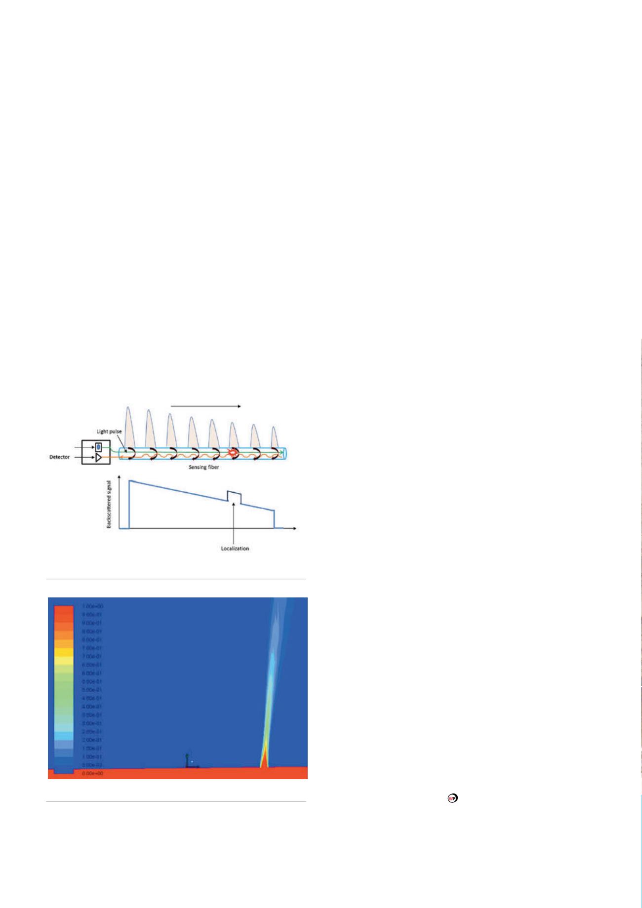
acoustic signature. The Rayleigh backscattering principle is
used for measuring acoustics in the DAS. Basically, this is a
counter-propagating phenomenon where the backscattered
light keeps the same frequency and speed as the source, but
travels in the opposite direction.
When there are no leaks in an environment, there are no
short scale time differences that would cause any change to
the backscattered signal. However, in an environment that
is leaking, the defects that cause the backscatter are subject
to the incoming pressure waves that then modulate the
backscatter signal. This signal can be analysed to recreate the
original backscatter signal and, as the system is pulsed, the
received signal can be sampled at a rate that corresponds to
the desired system resolution. For a useful level of backscatter
modulation to be analysed, there must be good transmission
conditions and contact between the leak-generated acoustic
wave and FOC.
The DAS uses a monitoring instrument at one end or either
ends of the pipeline and two or more fibres within a FOC for
pipeline leak detection. Acting as a distributed hydrophone
system, the FOC picks up the acoustic waves produced by a
leak. When a sound signature associated with a pipeline leak is
detected, a leak alarm is triggered with information about the
leak location.
These Rayleigh-based DAS systems can monitor up from
45 - 50 km without repeaters and with one instrument at one
end of the pipeline. However, ambient noise in the Arctic
pipeline needs to be calibrated so any leak-generated noise
can be detected and separated. Since the DAS system does
not require the cable to contact the leaking fluid, it may be
an ideal system for buried pipeline applications. Even so, the
sensitivity of the DAS to detect a small, chronic leak may be
affected by several factors including spatial resolution, soil
conditions, cable positions, length of coverage, strength of
leak, distance from the leak, background noise, the ability
to discern acoustic signature of the leak and internal versus
external pressures.
Challenges to the emerging FOC technology
While FOC leak detection systems show promise, they are
still emerging technologies and additional research and
development is needed. No independent performance
testing on hardware or software in the field or a simulated
Arctic environmental condition has been reported nor has
the reliability of a DTS or DAS system yet been proven in a
simulated Arctic environment or the field.
Questions that need to be addressed include baseline
parameters for false alarms, the reliability of the systems
in Arctic environments, establishing minimum thresholds
of detection, how installation and maintenance will be
accomplished in the harsh environment and additional design
measures which may be needed to maintain the orientation of
the cable, with respect to pipeline, during installation and on
the seabed.
If Arctic pipelines are longer than 50 km, inline
interrogators, repeaters and/or amplifiers will be needed
to maintain the system in the pipeline. A longer distance
could prevent the use of more interrogators that, in turn,
will increase costs as well as bring additional installation and
maintenance issues. Currently, no marinised interrogators are
available to the market.
Conclusion
Fibre optic LDS may prove to be the ideal systems for Arctic
pipelines since internal LDS have limited capabilities to detect
and locate sub 1% leaks. We eagerly anticipate that the further
research and development to answer the technological
challenges that fibre optic LDS in the Arctic and other harsh
environments still face. Currently, ongoing joint industry
projects (JIPs) indicate that the industry is evolving towards a
reliable technology towards oil spill detection in the Arctic
and sub-Arctic conditions.
Figure 3.
FOC pipeline leak detection principle.
Figure 4.
Pipeline leakage model in CFD.
22
World Pipelines
/
JANUARY 2015


