to schedule delays, or increased installation costs for pipe-
in-pipe (PiP) systems, or routing around environmentally
sensitive and high consequence areas (HCA). Advancements
in conventional pipeline LDS continue to be made due to
the demand for improved health, safety and environmental
performance.
With the push towards the Arctic and other harsh
environments, conventional remote sensing of small leaks will
become more difficult. Small chronic leaks below a minimum
LDS threshold might stay undetected during the winter ice
coverage, and a significant volume of oil might be released
without the ability for cleanup under optimal working
conditions during the two to six month summer window of
opportunity.
A closer look at fibre optic cable systems
Of all the LDS technologies that have been considered for
Arctic use, fibre optic cable (FOC) distributed sensing systems
show clear promise for detecting these small leaks. FOC
distributed sensing technology has been used successfully in
other industries, but has had limited use so far in monitoring
Arctic pipeline leaks.
With FOC continuously placed along the pipeline, multiple
sensors are unnecessary. The FOC placement provides a
backscattered signal at the source when parameter anomalies
are sensed. The presence and location of the leak can then
be determined by analysing the backscattered signal at the
receptor and the information communicated in real time to
the control room.
The optical time domain reflectometers (OTDR) principle
is used to determine leaks in FOC distributed sensing systems.
An optical signal is emitted into the fibre and a sensor receives
and measures the light backscattered to the source. An
exponential decay with time is the result of linear attenuation
in the cable and this shows up in the signal. The backscattered
signal carries the thermal and acoustic anomalies of the sensor
cable. Once these signals are analysed at the interrogator, the
presence of the leak can be detected. With the time interval
between the emission and backscattered detection, the
distance to the leak location can also be found.
DTS systems sense temperature changes
Pipeline leakage generates a local change in temperature – oil
leaks produce a local warming of the environment while gas
leaks produce local cooling. With FOC, these changes can
be captured by FOC distributed temperature sensing (DTS)
systems with good spatial and temporal resolution. Inelastic
Raman and Brillouin backscattering principles are used for
measuring temperature in DTS.
In Raman systems, thermally activated vibrational modes
of FOC sensor medium result in spontaneous inelastic light
scattering with the phonon population following Bose-Einstein
statistics. By measuring the light signal powers scattered at
the higher frequency (anti-Stokes) and Stokes wavelengths,
information about the leak-generated temperature at any
point along the fibre can be obtained.
Brillouin scattering physically converts temperature and
strain vibrations along a sensing fibre into frequency shifts of
the backscattered light. With specific and dedicated cables
installed along the pipeline, leak detection by temperature
irregularities and ground movement detection by strain
variation can be found. Since Brillouin technology is insensitive
to the fibre attenuation changes over time, it is more robust
than intensity based detection methods for temperature
measurement. The Brillouin frequency shift characterises
scattering for the system since it is based on interactions with
acoustic phonons.
The Brillouin scattering is very sensitive to temperature
and the deformations experienced by the sensing fibre.
Acoustic velocity impacts the Brillouin frequency shift and any
change of this velocity will be observed as a spectral shift of
the resonance.
Brillouin systems can be used to detect pipeline leakage
up to 45 - 50 km. Typical spatial resolution is in the order of a
few meters and temperature resolution is less than 1˚C, so any
thermal anomaly (i.e. delta T) of that temperature range can be
detected and located by using the DTS technology. Any small,
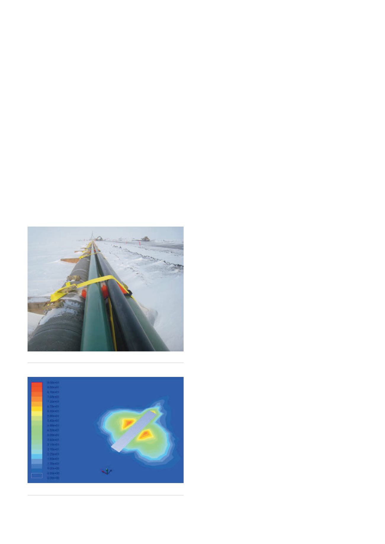
Figure 1.
Arctic pipeline bundle with FOC.
Figure 2.
Pipeline leakage acoustic contours.
20
World Pipelines
/
JANUARY 2015


