the rate at which the surface mobile layer is eroded and cuttings are
removed from the wellbore. There are many other factors at play, but
these are the dominant ones.
Prior to commencing any trip, it is necessary to first reduce the
cuttings bed height to an acceptable level, which will be defined by
the subsequent operation. If the trip is for a BHA or bit change, and
providing the BHA has been designed with good junk slot areas, then a
higher residual cuttings bed will be acceptable. However, if the trip will
be followed by the running of a tight clearance liner or a casing flotation
job, then a much cleaner wellbore will be required.
Performholecleaningcycle
Every trip out of hole should be preceded by a hole cleaning cycle,
irrespective of whether it will be performed on elevators or by
back‑reaming. A typical hole cleaning cycle would be as follows:
Ì
Before reaching section TD, condition the drilling fluid for optimal
cuttings carrying capacity.
Ì
Circulate a minimum of 3 ‑ 4 bottoms up, continuing until the shakers
are clean.
This must be performed with parameters (flow rate and
string rpm) in excess of hole cleaning thresholds (Figure 1).
Use downhole vibration tools to establish a safe rpm range with
low whirl.
Reciprocate the drill string by a distance greater than that
between tool joints to disturb and assist with mobilisation of the
cuttings bed.
Pay particular attention to the surge pressure on the
down‑stroke.
Ì
Measure or observe the volume of cuttings at the shakers every
15 min. A second wave of cuttings may appear approximately
1 ‑ 1.5 times bottoms up after the hole first appears to clean up.
Ì
Rack back a stand each bottoms up to minimise hole enlargement or
dropping of inclination. If the formations are such that this is not a
concern, it may be preferred to eliminate this step to prevent cuttings
avalanching occurring each time the pumps are off.
Ì
Pull 5 ‑ 10 stands on elevators to check hole condition, monitoring for
over‑pull and hole fill.
If all is well, pump a slug and continue out on elevators.
Otherwise, run back to bottom and re‑assess. Note that a
cuttings bed will still be present, but with a reduced bed height
that allows the remaining cuttings to ‘flow’ through the junk slot
areas around the bit and stabilisers.
Tripoutonelevators
This is Merlin ERD’s preferred method for tripping out of hole, primarily
because it is considered to be lower risk than the alternatives,
back‑reaming or pumping out of hole. It also enables drag trending
to be performed, which is a simple but highly effective method for
identifying changes in the downhole environment during the trip,
allowing remedial action to be taken before problems occur.
Prior to every trip or casing run, a torque and drag (T&D) road‑map
is prepared. This is a graph which shows the theoretical hook‑load as
a function of depth, friction factor and operating mode (free rotating,
pick‑up and slack‑off weight), an example of which is shown in Figure 2.
The actual weights recorded during the trip are overlain on to this
graph to reveal the friction factor. Once a background trend has been
established, the trend should track the theoretical trend lines as the trip
progresses.
Any departure from this trend must be explained. A pre‑determined
maximum allowable over‑pull limit is set, which when reached will trigger
remedial action. At high inclinations (> 40˚), it should initially be assumed
that any over‑pull is due to a cuttings bed, until proven otherwise.
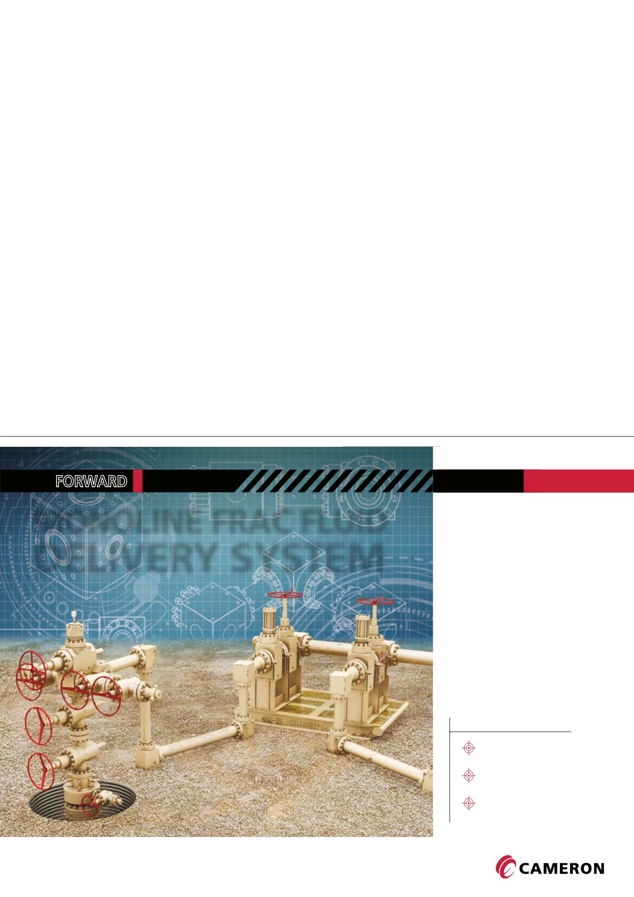
MONOLINE FRAC FLUID
DELIVERY SYSTEM
FRAC
SERVICE
WITH
The first of its kind, Cameron’s Monoline
™
Frac Fluid
Delivery System (FFDS) is designed with a single line to
enable quick installation and a significantly de-cluttered
work environment. A key component in CAMSHALE
™
Services’ Frac Rental portfolio, the FFDS moves the
industry forward through an innovative solution that
adheres to API standards and delivers a higher level of
system integrity and safety – all while reducing OPEX
and downtime.
Learn more at
AD01846SUR
The single line solution
that’s safer, faster and
cleaner than the
frac iron method
Monoline Frac Fluid Delivery System
H I G H L I G H T S
One line instead of multiple
Quicker installation
Less clutter at the well site


