20 |
Oilfield Technology
June
2015
Figure 3, for example, shows two realisations of possible
fault throws where Figure 3a and 3b have a larger throw on the
two leftmost faults than the realisation shown in 3c and 3d. Since
the fault uncertainty tool is integrated with structural modelling and
3D gridding tools, the user can rapidly build these models in full to
investigate the scenarios corresponding to the uncertainty in the
input data.
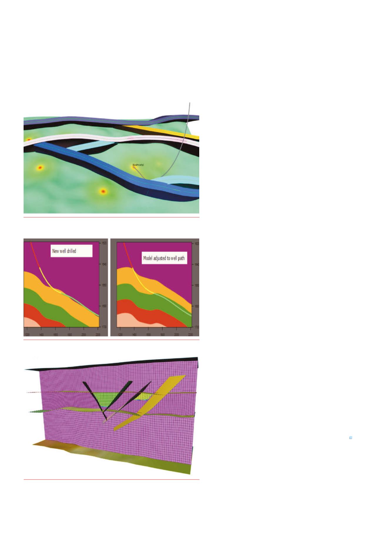
Faults can also vary within the fault uncertainty envelope and can
generate realistic structural scenarios with horizons also extrapolated to
ensure realistic results. Figure 4 illustrates fault uncertainty envelopes
and a map of reduced prediction error around wells.
Similarly, horizon uncertainty modelling enables the
incorporation of realistic uncertainties into the horizon models by
specifying uncertainties in the form of standard deviations for all
input data used in the horizon modelling process.
In this case, users are able to create horizons and zones based on
uncertainty data and information derived from well picks, velocities,
seismic travel times, and isochors.
The results of these uncertainty improvements are realistic
structural scenarios, the correct placement of horizontal wells,
improved volumetric sensitivities, and greater confidence in oil
and gas volume calculations.
Conditioningtowells
Where long horizontal wells exist, it is often difficult to correctly
condition the structural model to the zone logs due to the
lack of conditioning information and methods. An important
element of the horizon uncertainty modelling workflow
is therefore the ability to fit the model to a well path by
conditioning to the zone log automatically (Figure 5).
Grid construction also typically requires the balancing of
many constraints to produce a high quality grid and this may
not always honour well picks exactly. To meet this challenge,
the new workflow includes a new ‘Adjust to Wells’ tool that
supports the calculation of residuals between the grid and well
picks and can adjust the grid to exactly match the well picks.
Volumetricsensitivitystudies
Moving faults or horizons can change the volumes in place.
With the new fault and horizon uncertainty tools, volumetric
sensitivity studies are easy and straightforward to set up and
run. A range of different scenarios can be built and gridded by
simply varying the input parameters and running the workflow.
Figure 6 shows an example where the positions of the four
faults are allowed to move laterally within a predefined fault
uncertainty envelope. The volumes of interest are bounded by
these faults, a top surface and two contacts being different in
the two segments of interest, allowing output for the total field
or individual segments.
Conclusions
This article outlines a new workflow and set of structural
modelling tools that facilitate an ever closer relationship
between seismic interpretation and geological model building;
acknowledge realistic uncertainties in the data; and make it
faster and easier for reservoir modellers to build geological
scenarios and investigate the full effects of structural
uncertainty.
Through model‑driven interpretation workflow and the
integration of fault and horizon uncertainty tools with structural
modelling and 3D gridding, operators can look forward to
increased confidence on where to drill, what production
strategies to adopt, and how to maximise oil and gas recovery.
Bibliography
1. Georgsen, F., Røe, P., Syversveen, A.R. and Lia, O., ‘Fault displacement
modelling using 3D vector fields’, Computational Geosciences, 16, (2012),
pp. 247 ‑ 259.
2. Howley, E. and Meyer, R., ‘Developing an integrated structural modelling
workflow’, First Break 33, (March, 2015), pp. 95 ‑ 100.
3. Leahy, G. and Skorstad, A., ‘Uncertainty in subsurface interpretation: a
new workflow’, First Break 31, (September, 2013), pp. 87 ‑ 93.
Figure 4.
Fault Uncertainty envelopes andamap of reducedprediction error
aroundwells.
Figure 5.
Updating themodel by condition to anewzone log.
Figure 6.
The positions of the four faults are allowed tomove laterallywithin
apredefined fault uncertainty envelope. Differing contacts are illustrated in
two segments.


