HYDROCARBON
ENGINEERING
20
tank and foundation can only be designed if all
components are complete.
Soil data report
The first component, the soil data report, consists of
tabular and graphical results from both field and
laboratory tests. The report includes the properties of
each soil layer beneath the tank and within the zone of
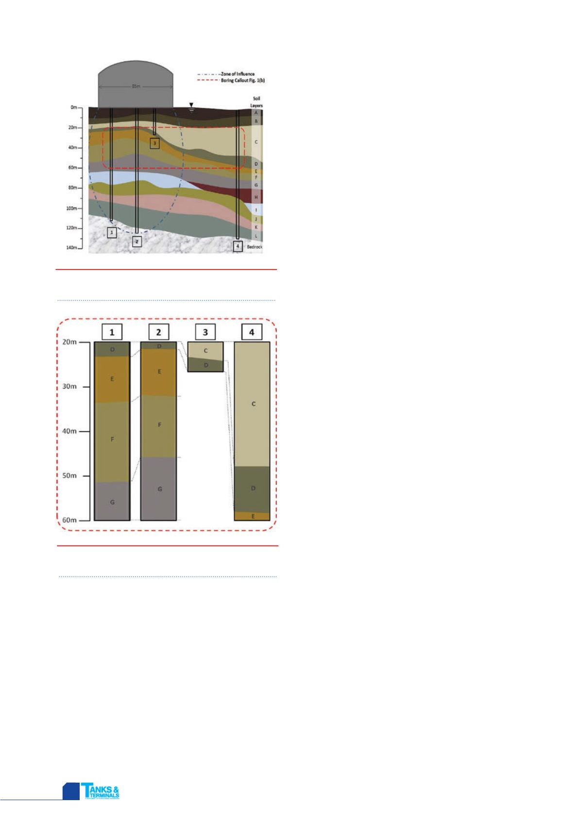
influence. Indicated on Figure 1 as a blue dotted line, the
zone of influence encapsulates the soil impacted by the
surface load exerted by the tank.
Soil in this area can be prone to excessive
consolidation if unable to bear the imposed tank loads.
This consolidation is of particular concern when a tank
settles unevenly, otherwise known as differential
settlement. As this occurs, stress and deflection increase
at the risk of compromising the tank’s structural integrity
and insulation systems. As differential settlement becomes
more extreme, the potential for permanent damage to the
tank increases.
Since the foundation design can accommodate a
certain amount of settlement, the soil properties
quantified in the soil data report are crucial when
calculating the predicted soil consolidation. These
properties include the gradation, relative in place
densities, consolidation rates, density and moisture
content of each soil type, and depth of each soil layer.
However, these samples, most commonly obtained from
borings, must meet a variety of requirements.
First, the depth of the samples must sufficiently cover
the zone of influence, usually 1.0 - 1.5 times the diameter
of the tank. As LNG storage tanks increase in size, required
boring depths will increase as well. Of the borings
illustrated in Figure 1, only Borings 1 and 2, at 115 m and
125 m respectively, would fulfill this requirement for an
85 m diameter tank. Shallow borings are unable to sample
the deeper soil layers and will reduce the accuracy of
settlement calculations.
Furthermore, the borings must be located directly
beneath the tank footprint. While Boring 4 in Figure 1 is
deep enough, its soil profile does not represent the soil
underneath the storage tank. For example, Layer H, present
in Boring 4, is not found in Borings 1 and 2, whereas the
opposite is true of Layer I.
Lastly, for a complete soil profile, enough borings must
be taken within the tank footprint. This captures the
potential variations in both soil types and soil layer depths
that may exist beneath the tank. As shown in Figure 2,
within a range of a few meters, noticeable differences in
soil composition are apparent; these variations can
translate to stressful differential settlement across the
tank.
By taking borings at the locations suggested in Figure 3,
differential settlement can be calculated without
excessive extrapolation. This allows the tank contractor to
adjust the foundation design by varying certain pile lengths
or using localised ground improvement.
Though Figure 3 provides guidance on the spacing
between borings, each project site is unique, and the
appropriate location and depth for each boring will differ
depending on site conditions. Therefore, enough flexibility
should be given to the geotechnical engineer to collect
samples that will adequately cover the demands of
designing both the foundation and tank.
Interpretative soil report
The interpretative soil report is the second component of
a geotechnical investigation and is built on the results
captured in the soil data report. The interpretative report
provides a qualitative analysis and discussion of the
subsurface conditions, as well as the geotechnical
engineer’s observations and recommendations for
foundation types and design parameters. Additionally, the
soil report will provide direction from the geotechnical
engineer to the tank contractor regarding alternative
Figure 1.
Example soil profile at the location of an
LNG tank.
Figure 2.
Example boring samples between depths
of 20 - 60 m.


