Dimensional metrology allows engineers to ensure that
precise specifications are met. Software comparisons of pipe
profiles improves weld speed and quality, thus helping to
reduce the time it takes to lay a pipeline.
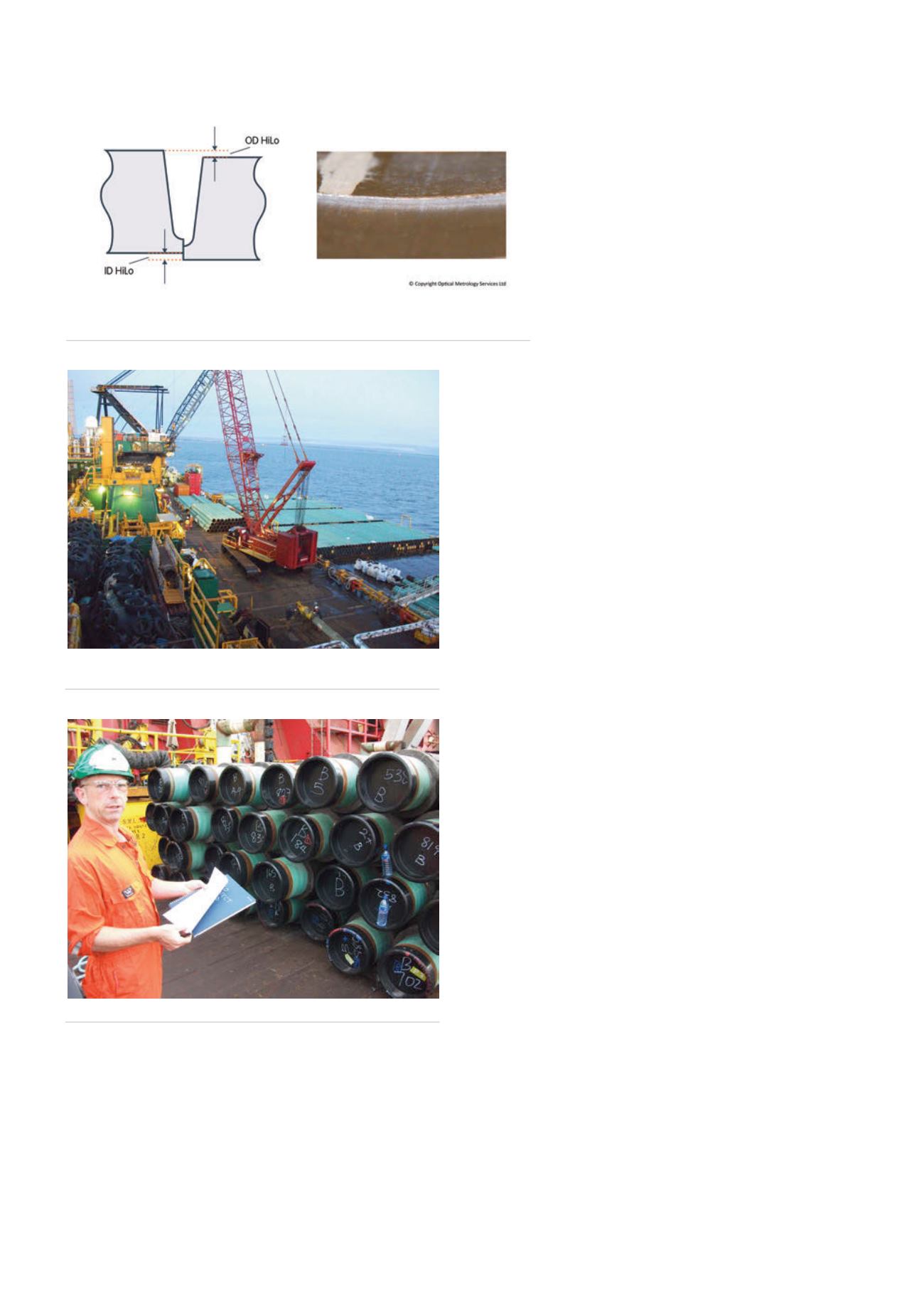
Internal HiLo misalignment
Tides, ocean storms, currents and swell create a highly
dynamic environment for the SCR, which in turn necessitates
design and fabrication processes that mitigate
stress and fatigue factors. There are a number
of highly critical aspects of the pipe fabrication
process that have to be guaranteed to be
correct. One of these aspects is the internal HiLo
misalignment between butted pipes (Figure 1).
Minimisation of HiLo contributes to a good
weld and decreases stress at the weld joint.
Typically, the HiLo misalignment is required to
be less than 0.5 mm in fatigue-sensitive pipeline
sections. In engineering terms this is a considerable
challenge, particularly given that the pipe used in
these applications is often seamless, which means
it inherently has wall shape and thickness deviations.
One method of dealing with HiLo misalignment is to
counterbore the pipes, but this might not be a viable method
of controlling pipe geometry due to cost considerations or
limitations on pipe wall thickness.
How can a pipeline contractor ensure that the pipe fit-up,
welding and pipelaying processes run smoothly with minimal
interruption? Managing risk is the answer. On occasions, a
pipeline contractor can receive ‘free issue’ pipe from the
project operator. Normally, these pipes will have been
sourced by the project operator from a pipe broker and, if this
is the case, the specific tolerance and geometric details of the
pipes are unknown.
So, how can a pipeline installation contractor be certain
that all the pipes for a project are within the manufacturing
specification? And, if they are, how easily will these pipes fit
together prior to welding and pipelaying in order to minimise
disruption in the welding and pipelaying process?
To prevent these kinds of bottlenecks, save costly
delays and minimise project risk, oil industry owners, pipelay
installation contractors and welders need to capture, record
and analyse pipe end geometry quickly and accurately.
Automatic, laser-based measurement tools are often used
to measure geometrical features of pipe ends, normally
performed onshore, although this process sometimes needs
to occur on a cargo barge. This measurement data, if used
correctly, can then help to ensure that pipes delivered into
the bead stall will fit together easily and within the welding
specification requirements.
Laser-based measurement tools can be used to measure
the IDs, ODs and WTs of pipe ends in rapid time. Typically,
several thousand ID and OD measurements of a pipe end
can be measured simultaneously in less than 10 seconds,
enabling hundreds of pipe ends to be measured in one shift.
In some circumstances, pipe ends can be measured in stacks.
This means less time onsite, less pipe handling (reducing
costs), minimising delays and costs for the pipelay contractor.
Laser measurement tools are also very accurate (typically to
0.05 mm).
Data from laser measurement tools can then be made
available to pipe optimisation software, which will include
some sort of simulation or sequencing capability such as
SmartFit™.
Winner of a Queens Award for Innovation in 2014, SmartFit
is a system developed by OMS for managing pipe preparation
Figure 2.
Pipes being loaded from a supply barge to the
pipelaying vessel.
Figure 3.
OMS Inspector numbering the pipe ends in the stack.
Figure 1.
Internal HiLo misalignment: minimisation of HiLo contributes to a
good weld and decreases stress at the weld joint.
94
World Pipelines
/
JULY 2015


