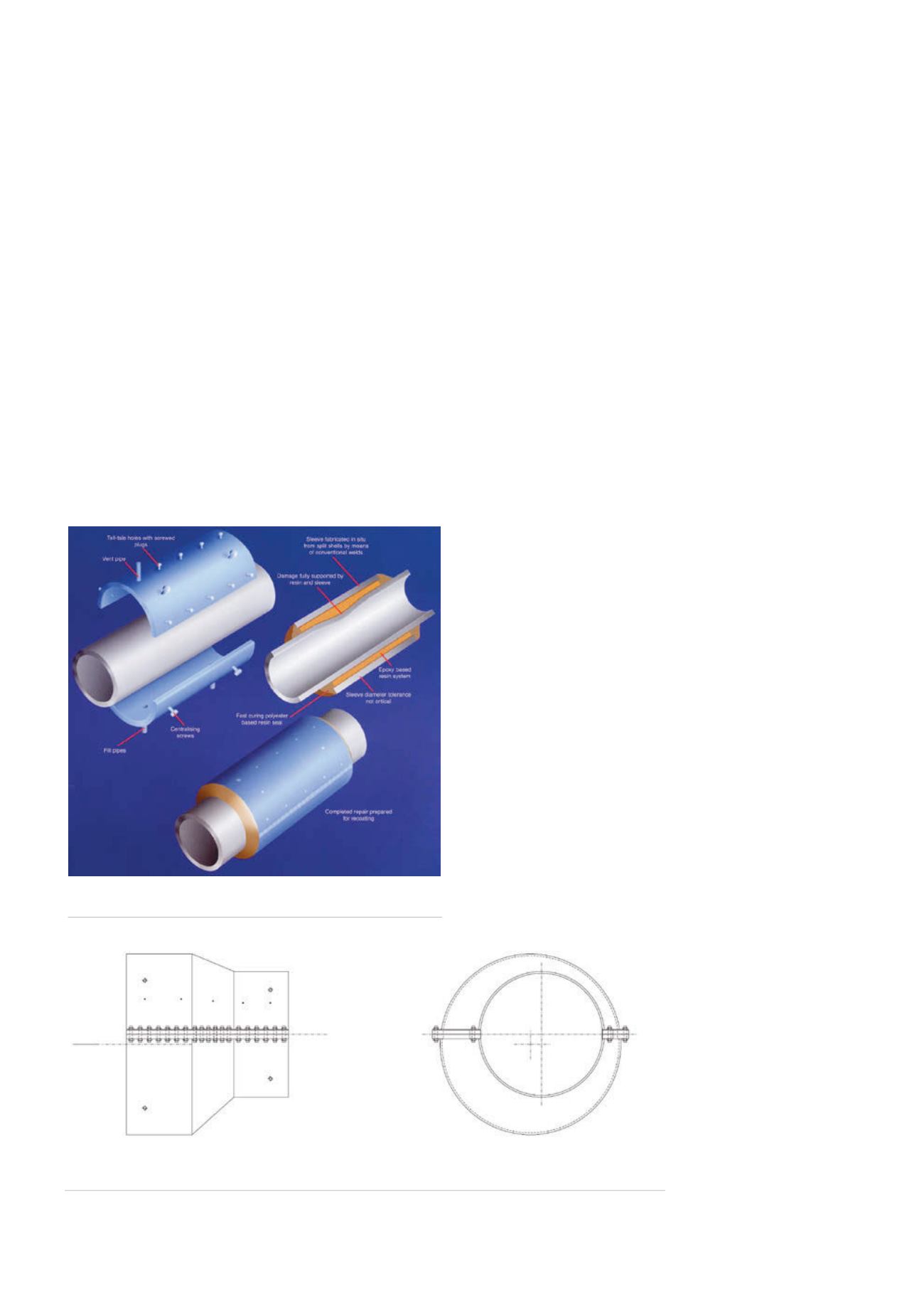
suitable for girth weld defects. The general layout of a welded
type epoxy sleeve is shown in Figure 2; this outlines the key
components of an epoxy repair sleeve.
Epoxy technology can be utilised for a variety of pipeline
applications. To date, operators have employed the technology
to resolve an array of complex problems. One of the beneficial
outcomes is an improvement in safety as there is no hot work
required on live pipelines, thereby removing the need for highly
skilled welders. Secondly, the risk of interruption to product
flow is limited and allows economic benefits to accrue to the
pipeline operators. Thirdly, difficulties arising from maintaining
temperature when conducting welding operations are eradicated,
allowing higher probability of scheduled installation and fewer
operational delays. Exact dimensions of each fitting are not
required prior to installation as much larger pipeline ovality can be
accommodated using epoxy technology.
Epoxy repair sleeves
The epoxy sleeve repair supports and strengthens damaged
pipelines without interrupting the product flow. Each fitting
comprises of two oversized half shells, which are either welded
or mechanically joined to fully encircle the damaged section
of pipeline, the annulus is then sealed at both ends prior to
injecting with epoxy grout. This results in a repair that is usually
stronger than that of the adjacent undamaged pipe material. On
completion of a repair, the shell can be linked to the pipeline for
cathodic protection.
The epoxy repair sleeve has also been designed for small
diameter applications typical of valve body vent and sealant
line corrosion. Sealant line repair sleeves have been qualified for
pressures of 689 barg (10 000 psig) in order to accommodate
sealant injection pressure. Lobster back repair sleeves can be
fabricated for all bend repair scenarios. These fabrications are
designed to match the wall thickness and material strength of the
bends and not the adjoining pipe.
In recent years, the epoxy repair sleeve has been adapted to
completely encapsulate damaged or corroded fittings by means
of a domed repair (Figure 1). The design is based on the principles
and concepts of the traditional epoxy repair sleeve. The branch
half shell has a welded dome end that is placed over the damaged
fitting and bolted, along the longitudinal flanges, to the lower
half shell. The remaining gap is then flooded with epoxy grout
providing a permanent repair to the pipe.
Epoxy end seals
In the 1960s and 70s, prior to the introduction of using thick wall
pipe for road crossings, thousands of steel sleeves were installed.
Multiple types of sleeves were deployed with many different
fills, including air, water, cementatious grouts, or thixotropic
materials such as bentonite, to prevent the ingress of soil and
water. Following the discovery of a number of instances of
excessive corrosion of sleeved pipelines, several investigations
were conducted around the corrosion protection systems and
a nitrogen charge into the sleeve annulus was introduced. This
created an inert, non-corrosive atmosphere for the carrier pipe,
and was considered to have many benefits over the grouts and
gels used at the time.
In order to achieve effective containment of the nitrogen
charge a rigid forged end seal was designed, which was intended
for use on future installations where a nitrogen fill was specified.
These forged end seals consisted of an annular ring with two weld
necks, designed to match the diameters of the carrier pipe and
sleeve.
In addition to the forged end seal, an epoxy end seal has now
been developed which allows
for retrospective nitrogen
filling of sleeves already
installed within a pipeline
network. The length, shell
thickness and flange thickness
are directly based on the
epoxy repair sleeve design.
The new end seal has
been designed to be installed
onto the pipeline at a
pressure of no more than
20 barg below maximum
operating pressure. The end
seal is designed so that it is
Figure 3.
General arrangement drawing of an epoxy end seal.
Figure 2.
Component diagram of a welded type epoxy repair
sleeve.
82
World Pipelines
/
JANUARY 2015


