Welding was carried out with only a few minor
issues encountered, attributable to fit up limitations of
the system related to an excessive root gap as well as
some observations on the gas shielding performance
on one of the test plates. No issues were encountered
that cannot be overcome by following good general
practice in setting up and subsequent housekeeping and
equipment planned maintenance.
Slag grinding is still required but the slag layer from
the flux cored consumable is comparatively fine and
exhibits self-detaching characteristics when used with
suitable parameters and joint configurations. Some post
weld brushing and grinding is still required to achieve
optimum weld quality but this is significantly less than
typically seen for SMAW welding.
Mechanical testing and NDT
A full suite of mechanical test schedules were drafted
and issued for each test weld. These were orientated
around both satisfying the qualification requirements of
the specification as well as testing additional areas and
regions of specific welds for complete characterisation.
The positional considerations of the plates and resultant
nominal heat inputs were also considered during test
specimen extraction to fully account for how these may
potentially influence mechanical properties. This was
to ensure that the test welds were able to stand as full
weld procedure qualification records (WPQR), as well as
being able to characterise specific regions of the weld
of general interest, and to assist in proving the concept
of the system and highlight any concerns or operational
limitations when used with typical spilt tee sleeve
materials. Example mechanical test results from the PA
position WPQR are presented in Figure 2 to Figure 5.
Once completed welds had been assessed using the
magnetic particle inspection and manual phased array
NDT techniques and progressed to the mechanical test
stage, the test extraction was monitored closely to
both optimise test coupon material for mechanical test
specimen extraction as well as ensuring selected regions
assigned for specific characterisation were captured.
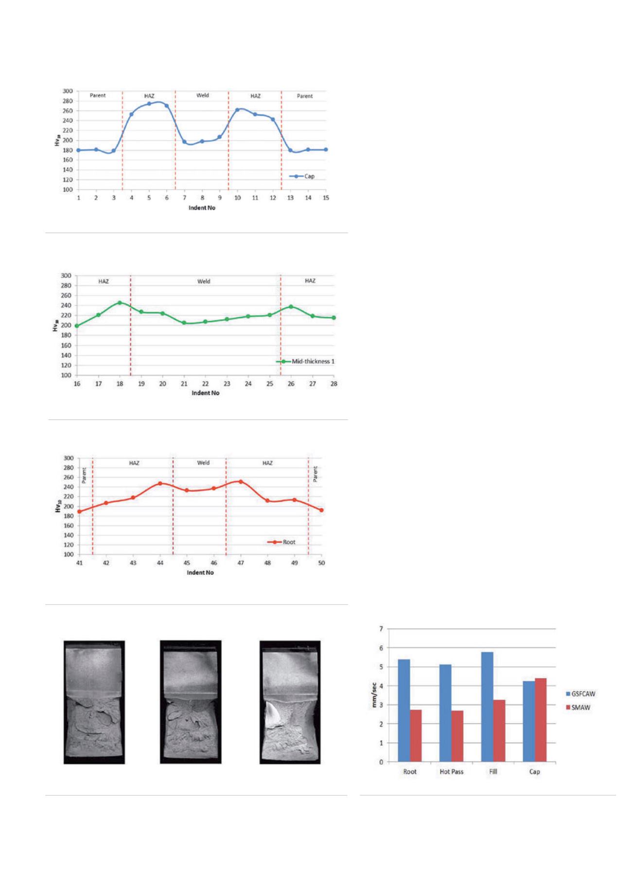
Figure 4.
PA mid-thickness hardness survey results.
Figure 5.
PA root hardness survey results.
Figure 3.
PA cap hardness survey results.
Figure 6.
Fracture faces from the HAZ CTOD tests.
Figure 7.
GSFCAW vs. SMAW welding times.
54
World Pipelines
/
JANUARY 2015


