August
2015
Oilfield Technology
|
61
Ì
Ì
The new application enabled assessment of all possible PT
combinations. Instead of just evaluating the system setup actually
configured, all possible permutations were tested, and the best
candidate was highlighted. This capability is crucial to reach the
best decoding performance without wasting time or even creating
NPT.
Fieldexperiencewith improvedsystem
In recent years, the demand for HSMPT has continuously increased.
The first test for the improved HSMPT system occurred a couple of
years ago in the most challenging region with high-viscosity OBM and
made it possible to deploy the improved system on all installations
where HSMPT was in demand. The improved system continued to
evolve and the decoding process was further automated and simplified
to the point that the jobs were supported by the standard rig teams. At
that point, and with the good track record of the improved HSMPT, the
use of the system increased on several of rigs as well as the confidence
in the positive results.
The improved HSMPT system has been used on many different
offshore installations in challenging deepwater environment with
high-viscosity OBM, and the TS could be reliably found on all of the
rigs, under almost all drilling conditions, with all mud systems and at
all depths. Especially significant improvements were achieved in the
smaller diameter hole sections.
For a more-detailed evaluation of the field performance, a subset
of data sets considering more challenging conditions is assessed.
Figure 3 shows the automatic detection performance for the TS.
The new system adjustments result in a clear improvement over the
previous system. This performance is considering single instances
of the TS without manual interaction needs. Together with the
consideration of mostly challenging conditions, it shows the potential
of the new system.
An operator placed a high priority on using HSMPT in a reservoir
section offshore, after having previously experienced significant quality
improvements in a drilled reservoir in the same field, due to increased
quality of real time data supplied while drilling. The service company
committed to run with high-speed telemetry in this challenging
environment and relied on the new features of improved HSMPT system
tomake the difference. A BHA similar to the one used in previous
reservoir sections was also deployed in this section. This BHA included
a steering unit along with the following services: drilling dynamics,
azimuthal gamma, resistivity, azimuthal density, porosity, nuclear
magnetic resonance, acoustic and formation pressure. The oil-based
mud used was also similar to that of the previously drilled sections,
having a density between 11.0 ppg and 11.8 ppg and a plastic viscosity
between 18 cP and 22 cP. A shallow-hole test was performed, and
good calibration parameters were generated from the first transmitted
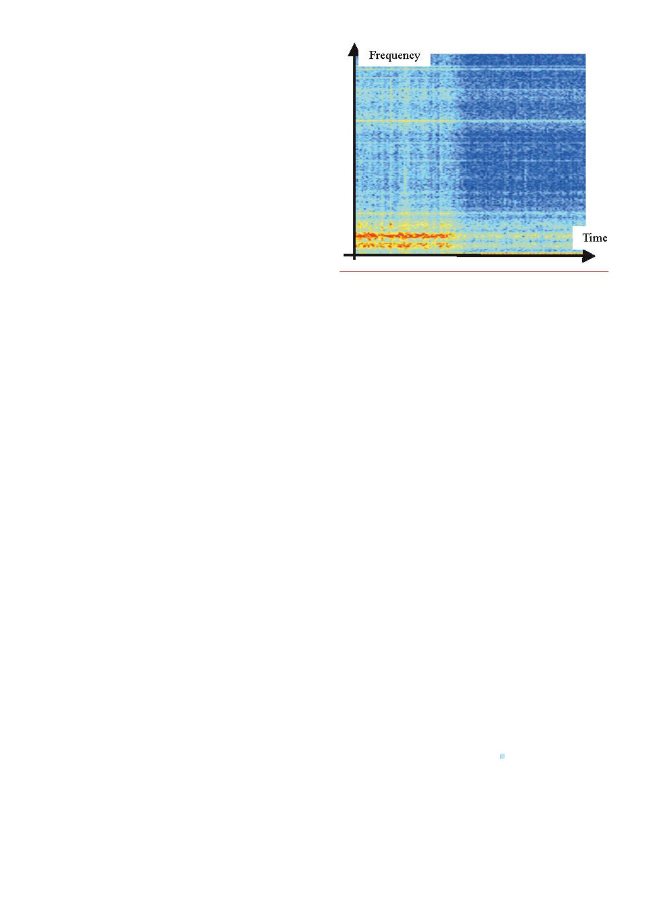
training signal. Figure 4 shows a spectrogramof the first set of data
from that shallow depth, where strong signal content is depicted in
red, while weaker signal content is shown in blue. The high-frequency
signal components are still visible. This set of coefficients delivered good
decoding performance while drilling the first stands.
By utilising the new HSMPT, the longest slim hole section of this
field was drilled. It covered over 2000 m of reservoir section. More than
90% of the reservoir section could be drilled with a high data rate.
Drilling this section was very challenging due to high torsional and
lateral vibration levels, which caused considerable downhole drilling
noise. The impact of high stick/slip values on the MPT signal can be
seen in Figures 5 and 6. A high-energy, low-frequency wave interfered
with the telemetry signal and had to be cancelled out. Both figures
show approximately the same content. The distortions of the pressure
signal created by stick/slip can be clearly seen in Figure 5 in the time
domain. Figure 6 shows the impact on the frequency content of the
MPT during this time period. Stick/slip adds as a dominating distortion
in the spectrum, weakening higher frequency contents.
The advanced filtering and processing methods introduced by
the improved HSMPT systemmade it possible to deliver sustainable
HSMPT data rates even with high vibration levels. The improved
training signal detection rate allowed for more frequent updates
of the adaptive filters, which in turn led to the robust delivery of
the required data rate. The success rate of the training sequence
detection reached 95%.
Conclusions
HSMPT systems enable the drilling of wells in conditions where
high-density directional, downhole pressure, drilling dynamics and
formation evaluation data is critical. However, there are still challenges
with the reliability of HSMPT systems.
The improved HSMPT system addresses these reliability issues and
provides:
Ì
Ì
Significant improvement in the detection of the TS with
introduction as new hardware and software solutions and
automation of the detection process.
Ì
Ì
Tremendous improvement of the reliability of the TS detection in
previously challenging environmental conditions.
Ì
Ì
Automatic evaluation of the new coefficient sets for decoding
filtering, even in constantly changing communication channel
conditions.
Ì
Ì
A database of coefficient sets to assist the FSE through automated
saving of the sets with corresponding additional information.
Ì
Ì
The assessment of all possible pressure transducer combinations
with testing of all possible permutations and highlighting the best
candidate.
The improved HSMPT system is successfully tested in several
deepwater areas as with WBM and OBM systems and demonstrated a
significant increase in reliability of HSMPT.
References
1.
Proakis, J. C., ‘Digital Communications, fourth edition’,
Singapore: McGraw-Hill, (2001).
2.
Klotz, C., Bond P. andWassermann I., et al., ‘A newmud pulse telemetry system for
enhanced MWD/LWD Applications’, Paper SPE 112683 presented at the IADC/SPE
Drilling Conference, Orlando, (4 - 6 March, 2008).
3.
Shen Y., Su Y., Li G., Li L. and Tian S., ‘Numerical modeling of DPSK pressure signals
and their transmission characteristics inmud channels’, PetroleumScience 6 (3),
(2009): pp. 266 - 270.
Figure 6.
Stick/slip severity change and impact on the power density
spectrumof the pressure signal. Reddepicts strong signal content, blue
showsweak signal content.


