Each individual section hydrotest should be risk assessed
and the operation controlled by a method statement. As
stated previously, safety of personnel, other contractors
and the public is of paramount importance when carrying
out a pressure test.
The main hazard associated with pressure testing is
the unintentional release of stored energy. The risk of this
happening is engineered out to a certain extent by the use
of sufficiently rated pipe material of the correct grade and
material quality. The other obvious method of ensuring
safety is to remove the risk to personnel. This is achieved
by excluding access along the pipeline spread to farmers,
construction workers, walkers, etc for the duration of the
hydrotest and maintaining a safe distance for hydrotest
personnel. Where the pipeline section terminates at
installations the protection of any live gas plant within the
vicinity of the pipe under test must be addressed. Blast
effects and distance of projectile travel can be estimated
(UK HSE GS4 Safety in Pressure Testing) to assess the need
for type of protection over test end or permanent pipe
fittings.
Equipment used for hydrotesting should be sufficiently
rated for its safe operation with a built-in safety factor over
that of the test pressure.
Equipment must be maintained good condition.
hydraulic hoses must have a suitable working pressure
above that of the test pressure applied and must be
inspected immediately before use as well as undergoing
visual internal and external inspection and pressure testing
to 1.5 times its working pressure, every six months. Hoses
visibly damaged, exposing the steel braid, should be
discarded.
For large volume test sections where high volume/high
pressure pumps are needed to pressurise to test pressure,
steel pipe should be used between the pump and test end.
Short flexible hydraulic hose should connect either end
of the pipe to remove vibration from the pump and avoid
fracturing the pressurising pipework. All hoses should be
anchored at intervals along their length to avoid whip in the
event of hose failure.
Provided the controls assessed as required by the
risk assessment are in place hydrotesting should be an
uneventful operation.
The pressurising pump output, section volume,
∆
V/
∆
P
(incremental change in volume/pressure), static head and
test pressure are calculated for each test section. For
pipelines designed to operate at a design factor of
<
0.3 the
test pressure is 1.5 x MAOP, with the pressure applied to
the highest point of the section. For pipelines designed to
operate at a design factor of
>
0.3 the test pressure is 105%
SMYS for the weakest (light wall) pipe section, with the
pressure applied to the lowest point of the test section.
Pressurisation is undertaken in stages. The air content
of the test section is assessed when pressurising from static
head to 50% design pressure. The air content of the test
section should not exceed 0.2% of the fill volume.
If the air content is acceptable pressurisation may
continue to the test pressure. A
∆
V/
∆
P plot must be
maintained. Should the rate of pressurisation deviate
by +/-10% from that expected the cause should be
investigated.
Care should be taken when approaching test pressure to
closely monitor the
∆
V/
∆
P plot for signs of double-stroking
(twice the calculated
∆
V/
∆
P) and pipe yield.
Once test pressure is achieved, readings of pressure,
pipe wall and ground temperature are taken at regular
intervals for the test duration. The criteria for test
acceptance is that there should be no observed pressure
variation, other than that accounted for by changes in
ground and pipe wall temperature. When testing to yield,
the allowable loss should not exceed 0.2 bar G over the last
three hours of the test.
Dewatering
Dewatering can be a hazardous operation due to air/
water mixture if operations are uncontrolled. High pressure
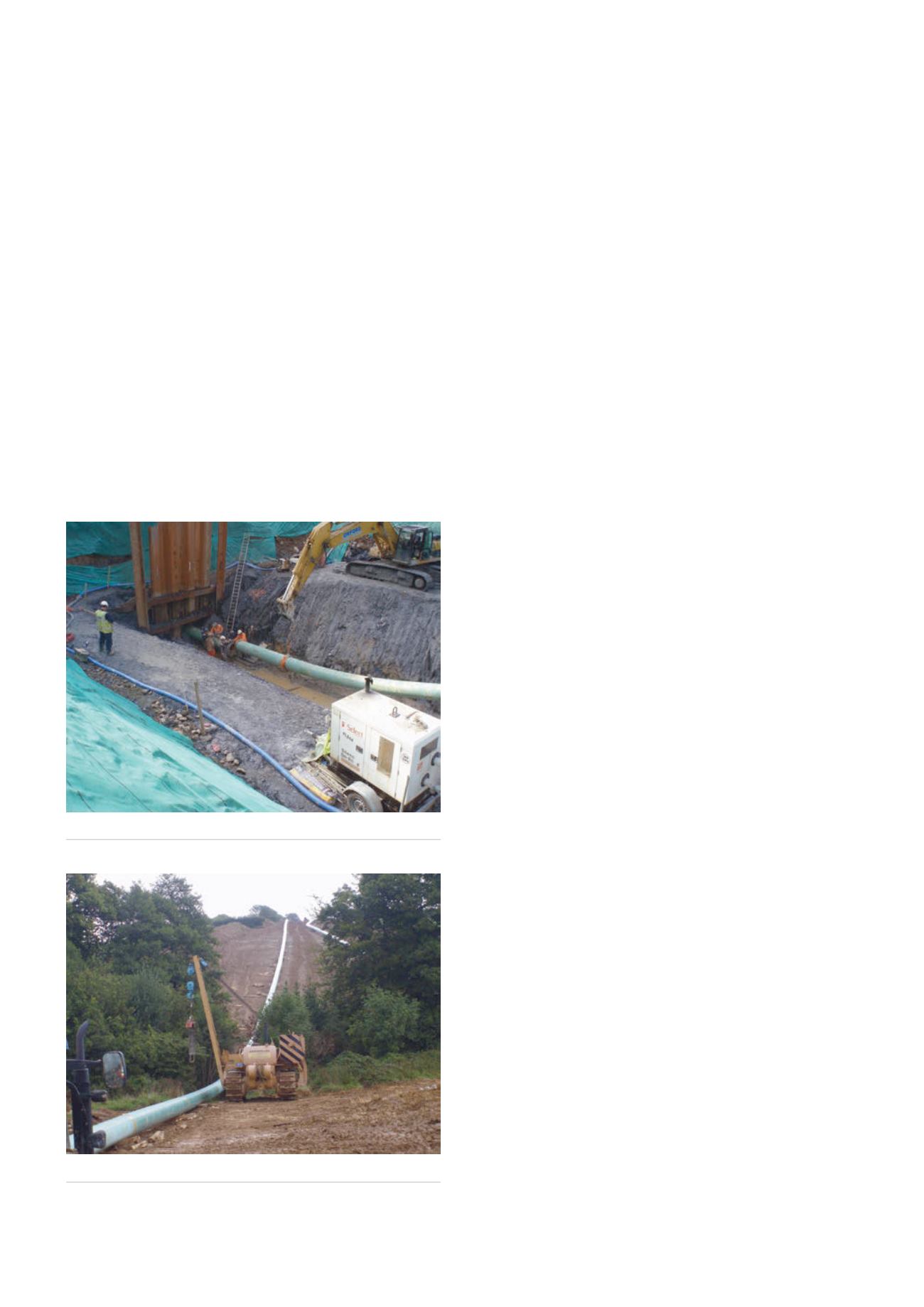
Figure 7.
HDD pre-test string
Figure 6.
Pipeline tie-in to HDD section.
174
World Pipelines
/
AUGUST 2015


